Project Jenny Photo Gallery
| Navigational aids: | Back to JP's Radio Homepage |
| Back to TMC Home Page | |
| Back to TMC History Page | |
| Back to TMC Photo Gallery Page | |
The objective of Project Jenny (also referred to within TMC as "Project 15") was to build a flying platform for TV and radio broadcast for troop entertainment and psy warfare. The project began in 1964, after several false starts, under the leadership of George Dixon, who had been acting as VP Sales for TMC (Dixon later became Executive VP in 1966). Dixon had been a Naval aviator and had retired, but was called back to active service to oversee Project Jenny. Dixon was quite an interesting character, to say the least, and it was no doubt his forceful personality that brought Project Jenny to life. John Showalter shared several amusing stories about the development of Jenny, which I'll add to this site once I've transcribed the notes of my long conversation with him!
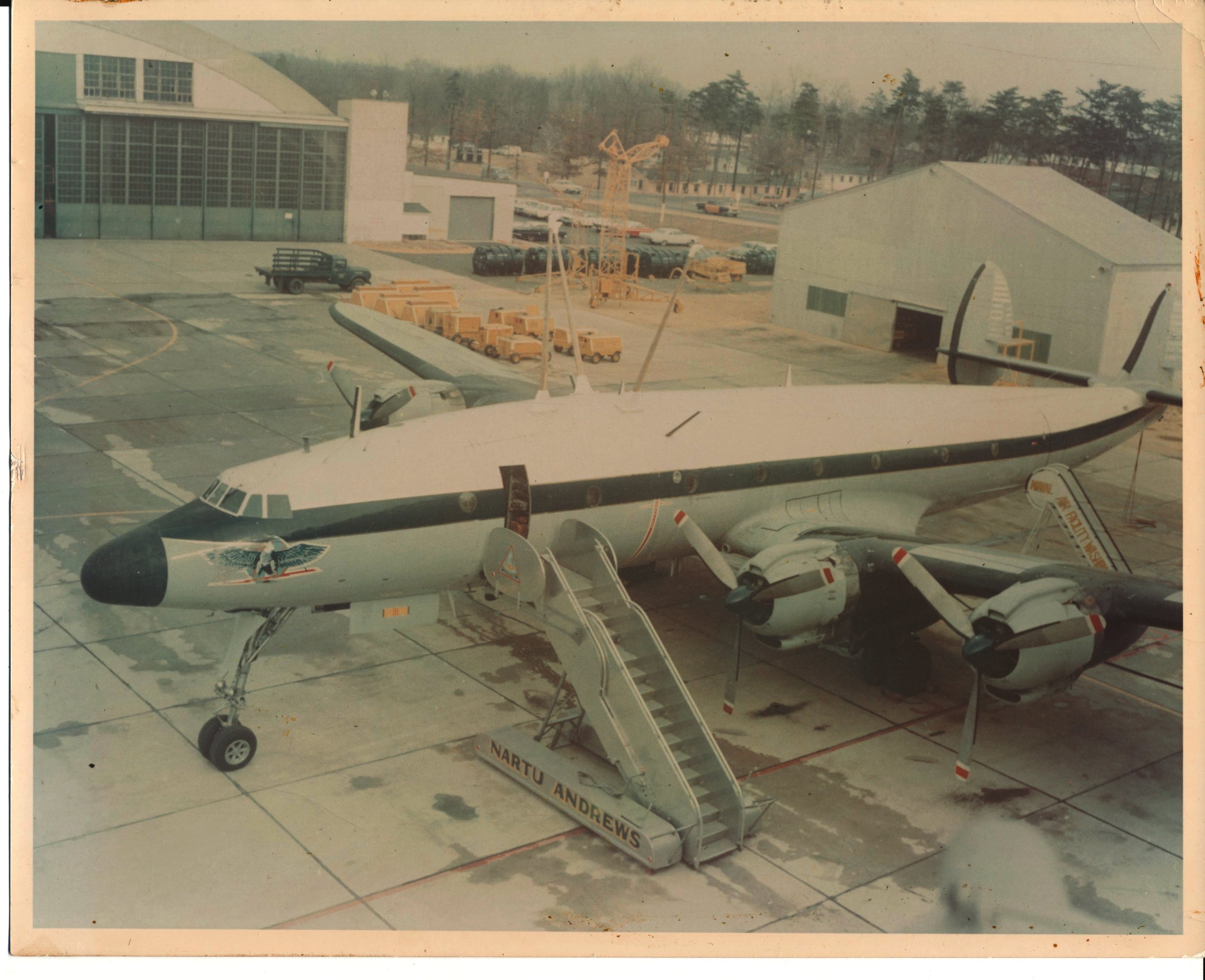
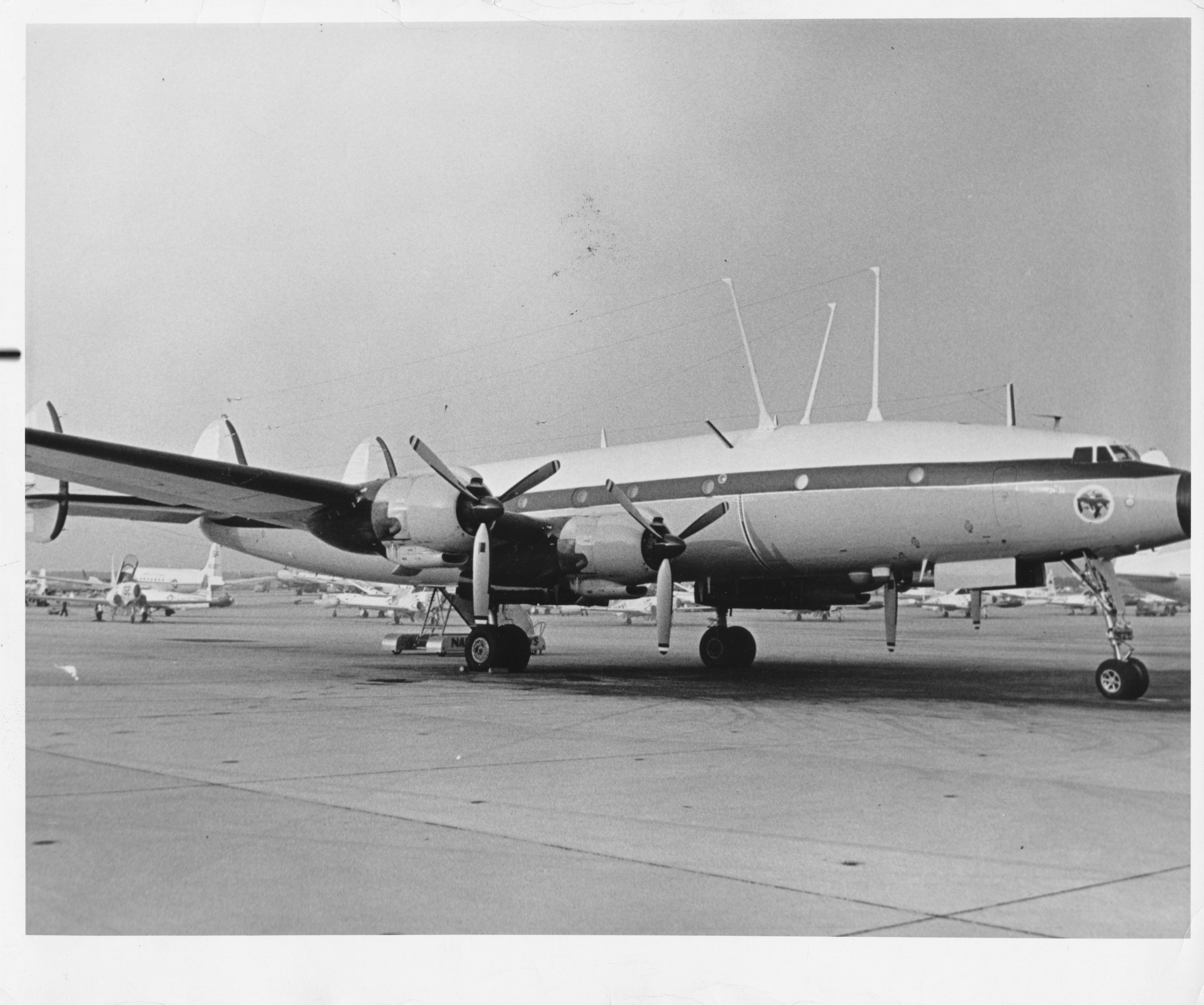
Jenny equipment included a GPT-10K, a 10KW LF transmitter, a trailing-wire antenna, a 3.5KW television transmitter, and essentially a complete TV studio. The first aircraft, Blue Eagle I (BUNO 131627), was a "radio-only" aircraft, whose initial configuration and development was overseen by Dixon at Andrews Air Force Base. Construction was performed by enlisted personnel, and at least one technician (John Showalter) from Multronics, Inc. Multronics designed and built much of the equipment on this aircraft, including the transmit multicoupler, trailing-wire antenna system, and attached HF antennas. TMC Power Systems built a special diesel generator that powered the equipment aboard the aircraft. It was located near the rear of the aircraft behind a "sound proof" partition (evidently the aircraft was incredibly noisy when all of the equipment was running!). The company also built a TV broadcast transmitter under contract to TMC. This equipment can be seen in the photo gallery below. Blue Eagle I is shown below:
This aircraft was equipped with three antenna systems:
Blue Eagle I must have been incredibly entertaining to fly. Apparently there is a commercial weight limit for the Connie, and a much higher Military weight limit. Blue Eagle was heavier than the full Military weight limit by quite a bit, requiring a very long takeoff roll and a very flat trajectory once the aircraft left the ground. Landings were similarly "interesting".
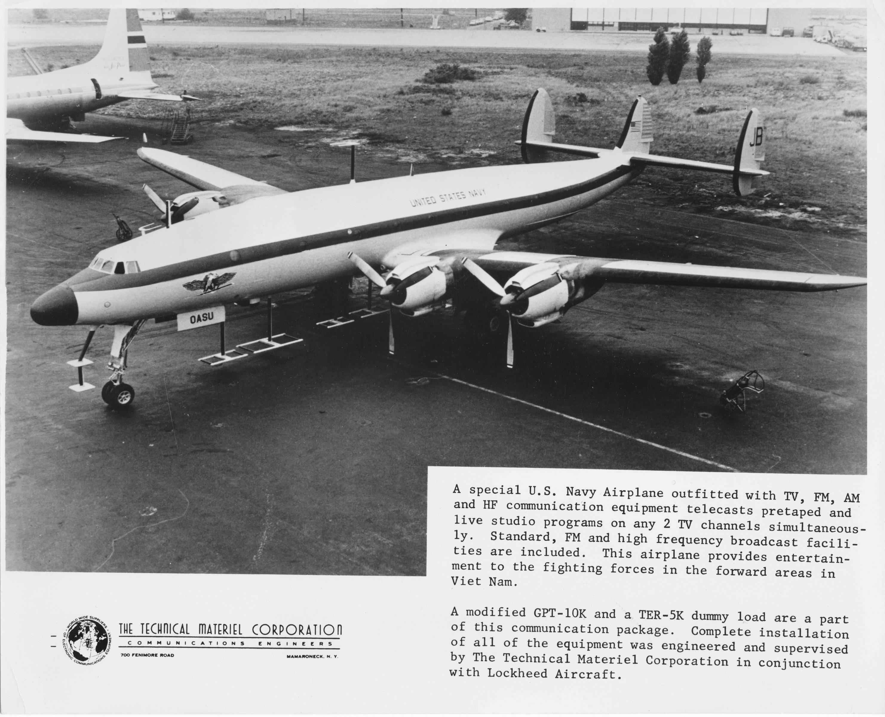
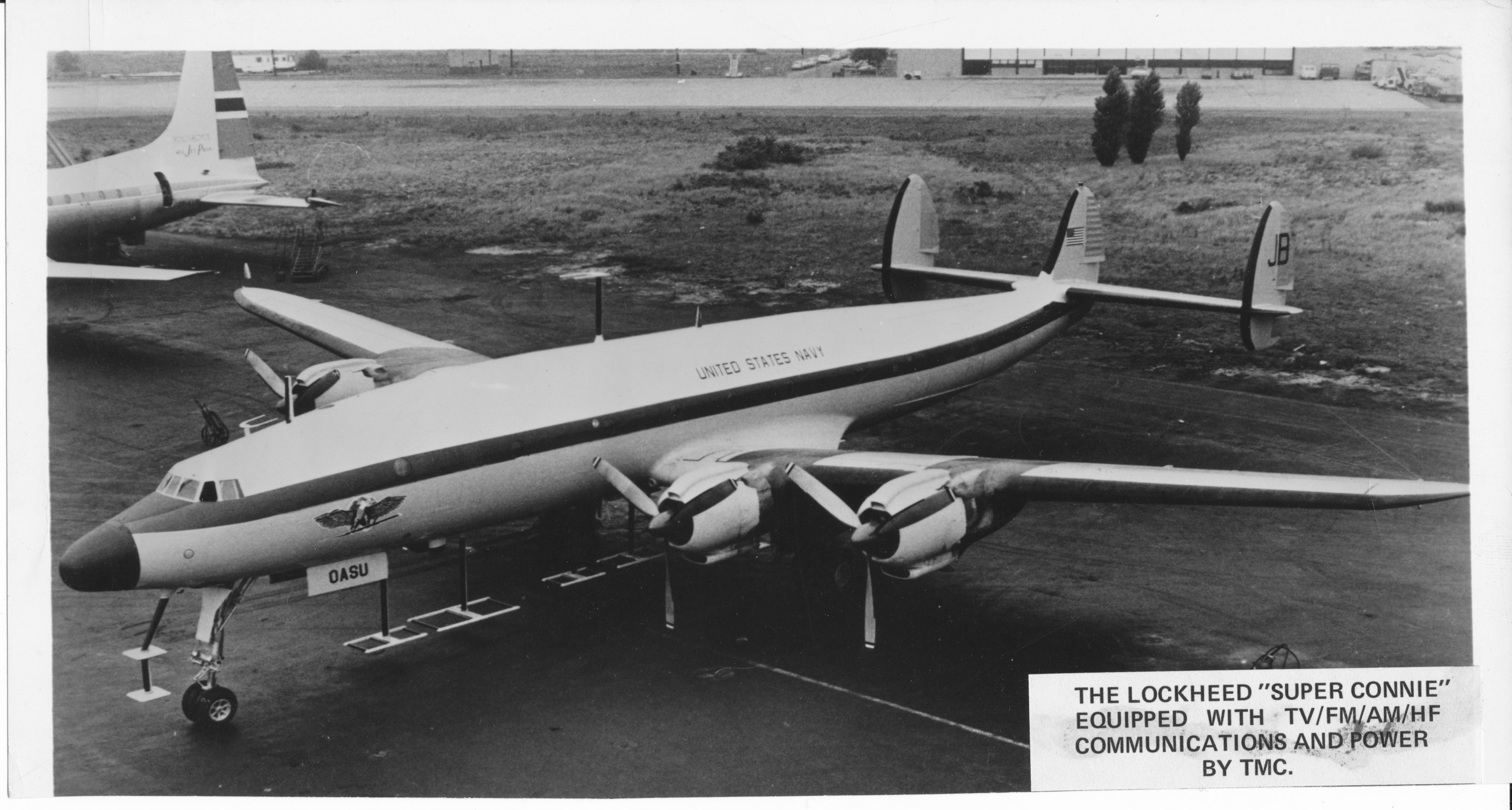
Blue Eagle II and III (BUNO's 131611 and 131429) were later assigned to the development effort to test various TV antenna configurations. I believe the photo immediately below may be one of these aircraft, though the antennas shown in the photo were not those that eventually were deployed in service. These later aircraft appear to have had some TMC equipment, including a TMC GPT-10K HF broadcast transmitter and HF communications gear. The television equipment was probably built by RCA, but evidence (the photos below from the TMC photo archive) suggests that the equipment racks containing communications and TV monitoring gear were probably integrated and cabled at TMC in Mamaroneck.
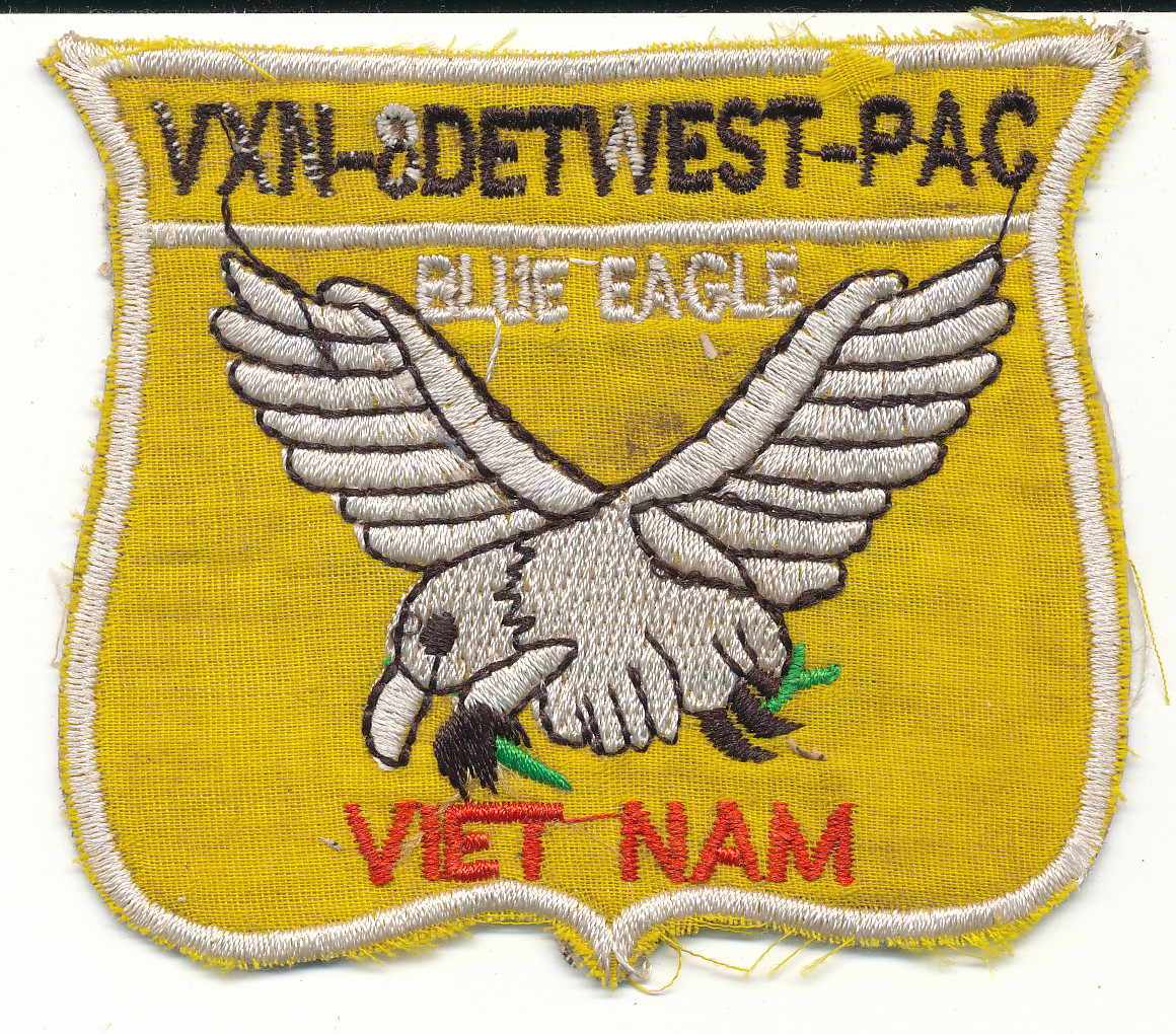
Eventually there were 6 Blue Eagle aircraft, flown by the VXN-8 squadron. There is lots of interesting information about the squadron on the Blue Eagle website. Below is a scan of the unit shoulder patch:
Project Jenny ended in the late 60's but was replaced by Commando Solo, a flying Psyops station aboard an EC-130J. See:
http://xbradtc.wordpress.com/2011/04/05/commando-solo/
http://www.hmdb.org/marker.asp?marker=12542
http://www.acus.org/content/interior-ec-130j-commando-solo-march-2003
A later, and perhaps current, incarnation is Coronet Solo:
http://www.psywarrior.com/ec130.html
In addition to a large number of photographs in the gallery below, I also unearthed a couple of interesting documents:
I am greatly indebted to John and Grant Showalter, who took time to discuss
Project Jenny with me at length and who loaned me a number of unique documents
about the project. If you have more information about Jenny that you can
share, please email me at ![]() .
.
|
 |
 |
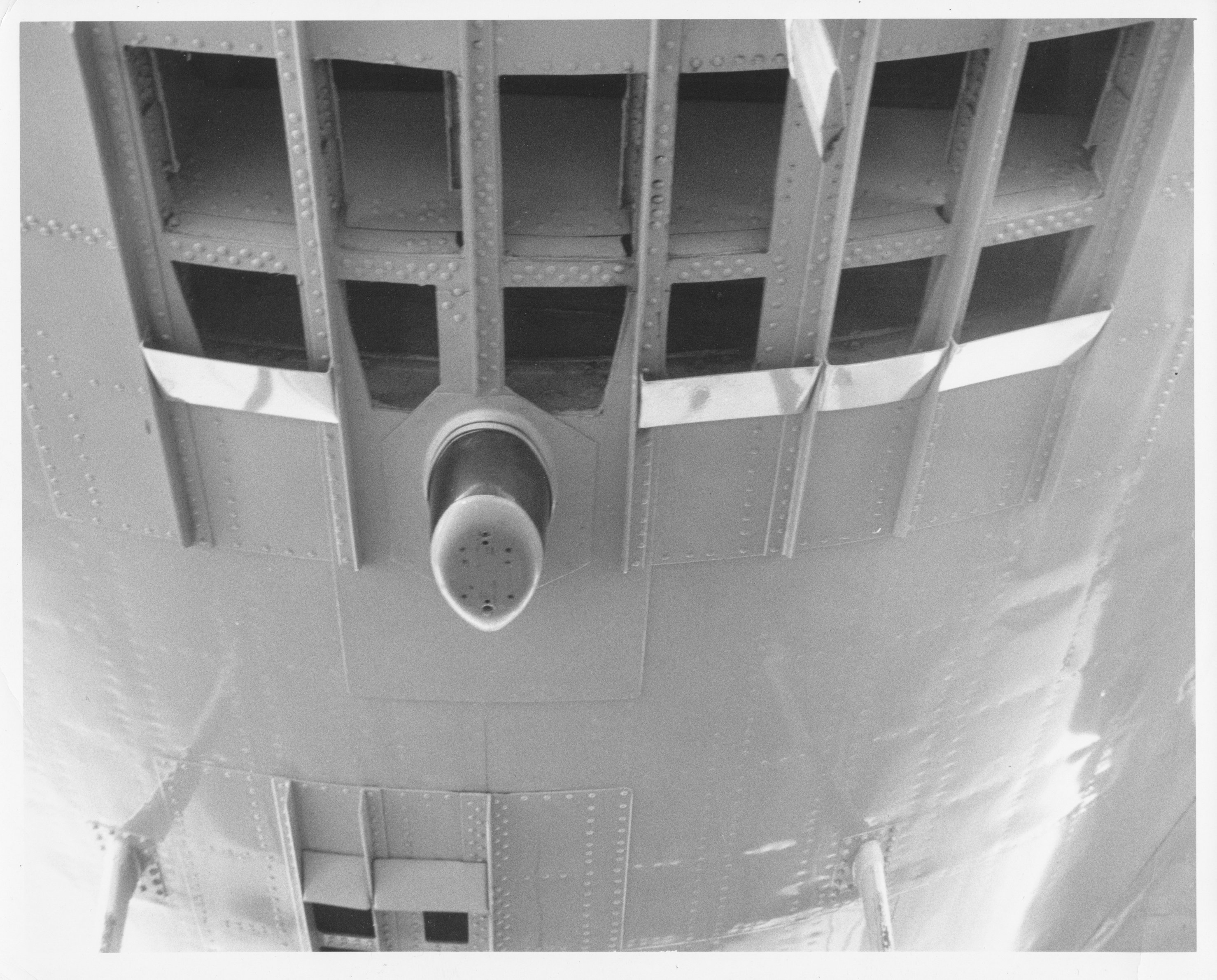 |
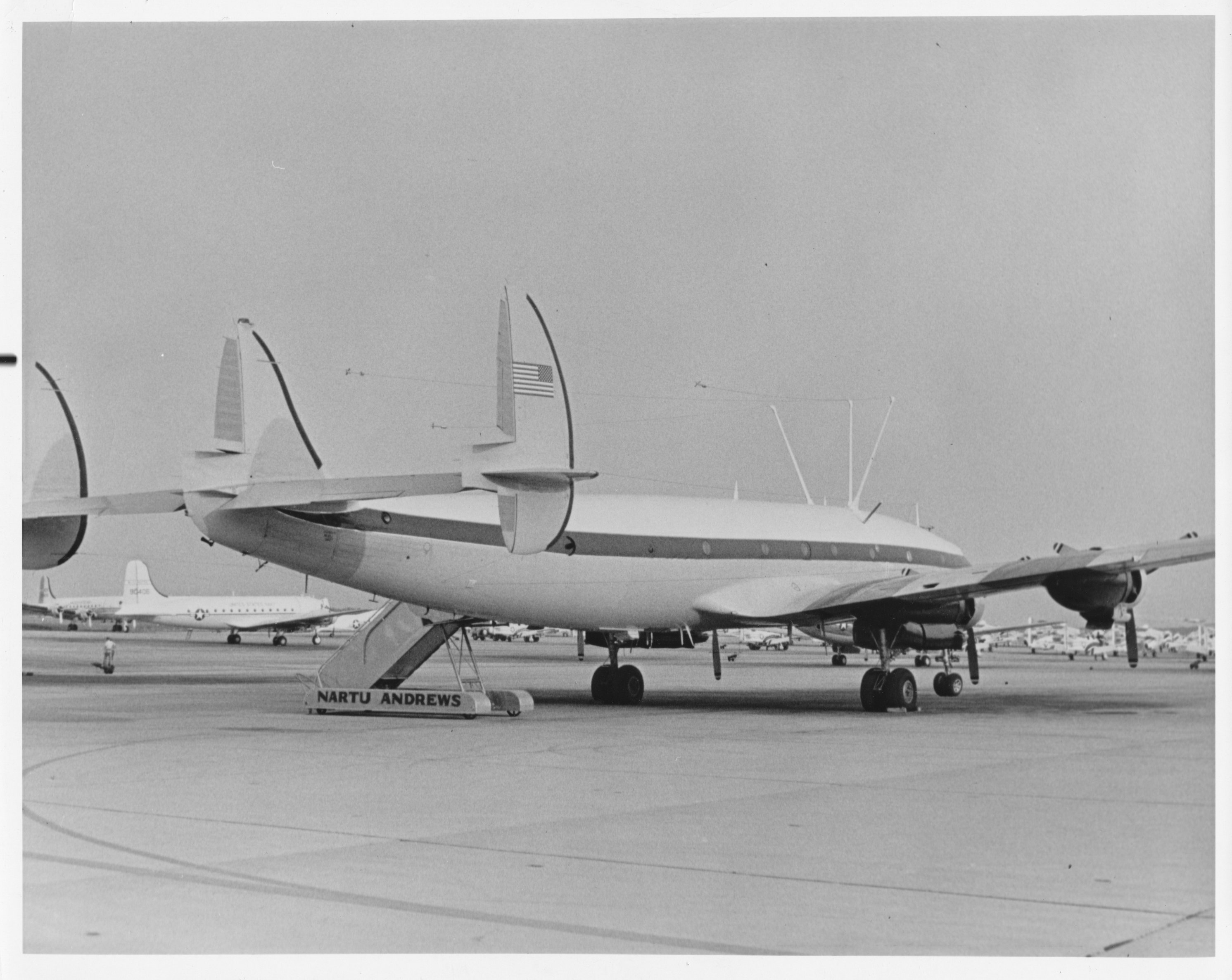
| This photo shows the television equipped aircraft. Note special TV antennas mounted below the fuselage. | Back labeled: "US Naval Air Station, Patuxent River, MD Photographic Laboratory. Official US Navy Photograph" This is almost certainly Blue Eagle I, the prototype aircraft. | Back labeled: "US Naval Air Station, Patuxent River, MD Photographic Laboratory. Official US Navy Photograph" This is also, most likely, Blue Eagle I. | Info about this feature on the underside of the fuselage is in my notes: I'll update it soon! |
 |
|
||
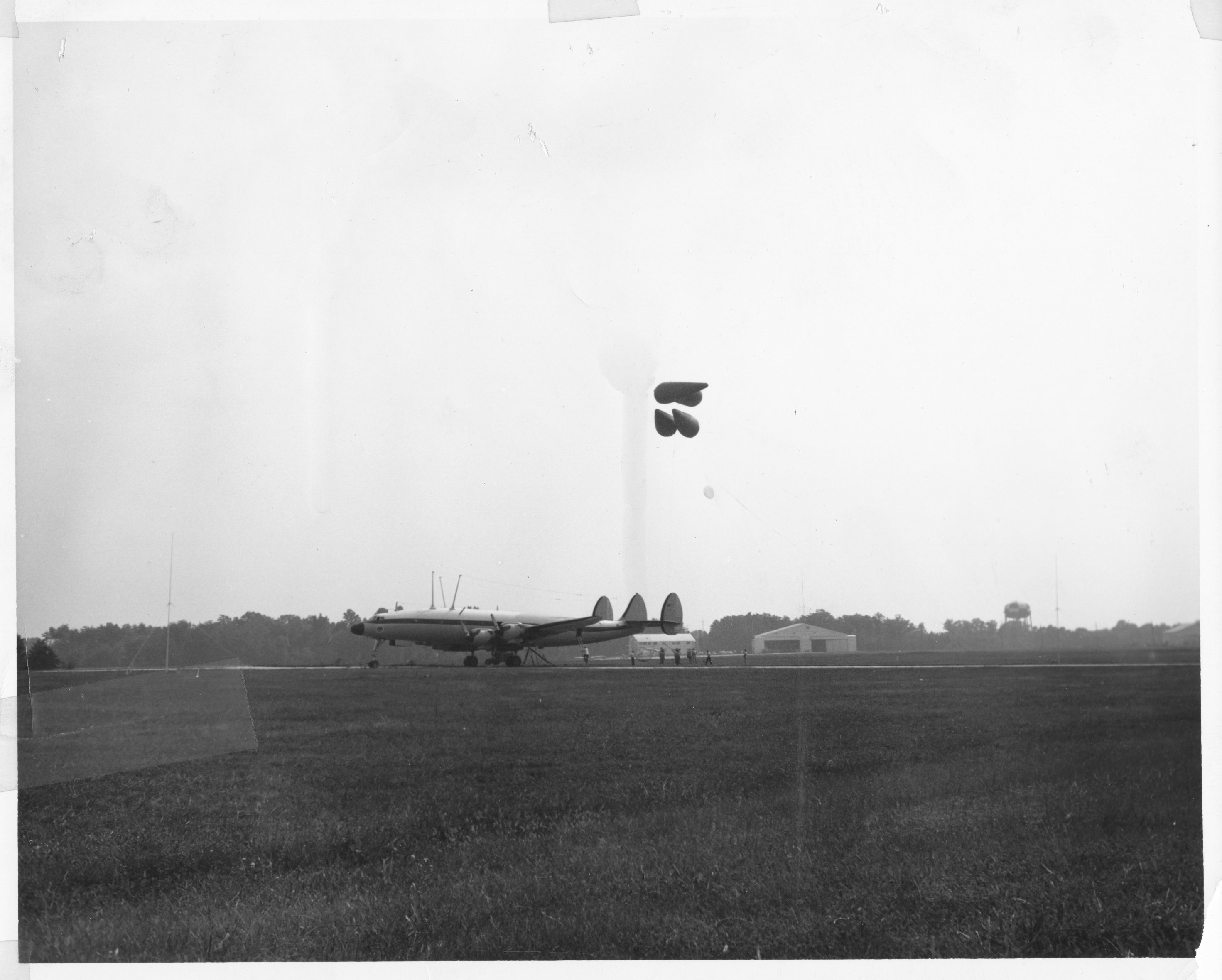
| This photo shows the balloon antenna system deployed. This was a backup plan in case broadcast from the plane while aloft turned out to be impossible. The trailing wire antenna passed below a clamp, then up to the balloons that took the antenna aloft. Just barely visible in forward of the aircraft is an HF vertical antenna that could be deployed on the ground. | Blue Eagle I. Note the insignia place directly below the fuselage. There are photos on the web relating to the Blue Eagle squadron that show this aircraft with "627"(last 3 digits of the BUNO) painted on the fuselage near the nose. |
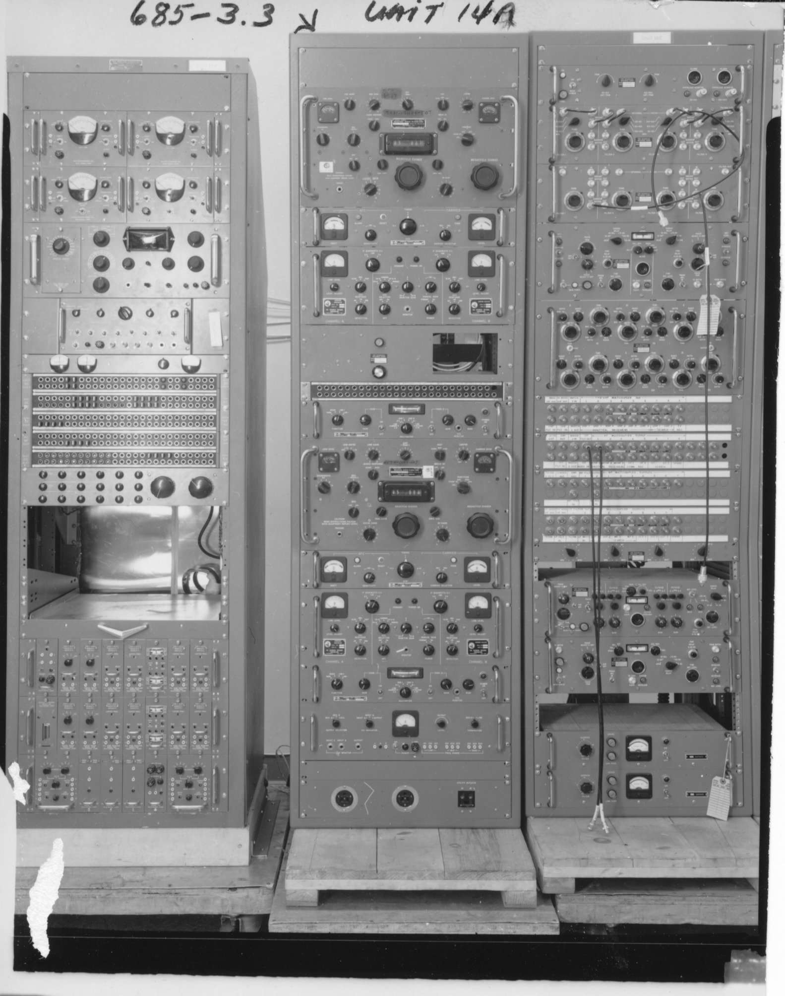
Below are a bunch of photographs of rack units evidently taken at TMC while they were in manufacture. Most are numbered, and I've referred to the rack number/letter designation where I have it.
 |
 |
 |
 |
| 6837-5 Unit 7A I believe this unit may have been a manual coaxial patch panel. A similar item is described in a Multronics manual supplied to me by John Showalter, and it is capable of connecting 3 transmitters to several antennas or a dummy load. | 686.5-5 Unit 11 | 683.1-2 Unit 11 | |
 |
 |
 |
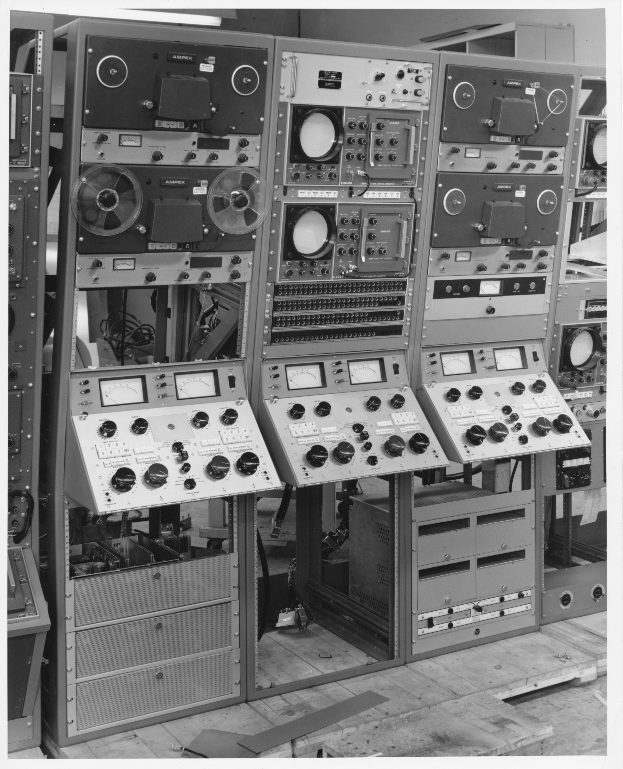 |
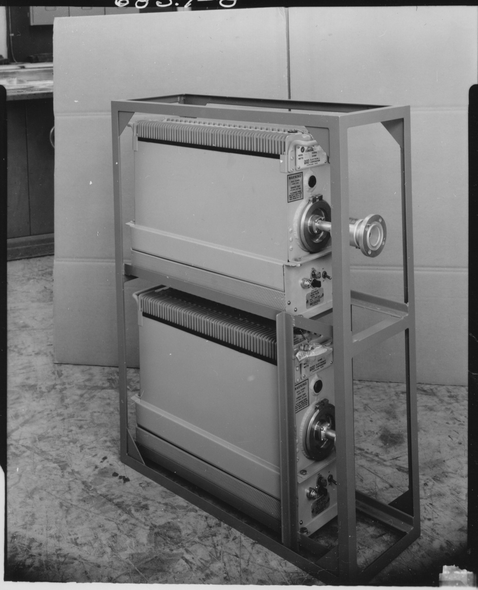
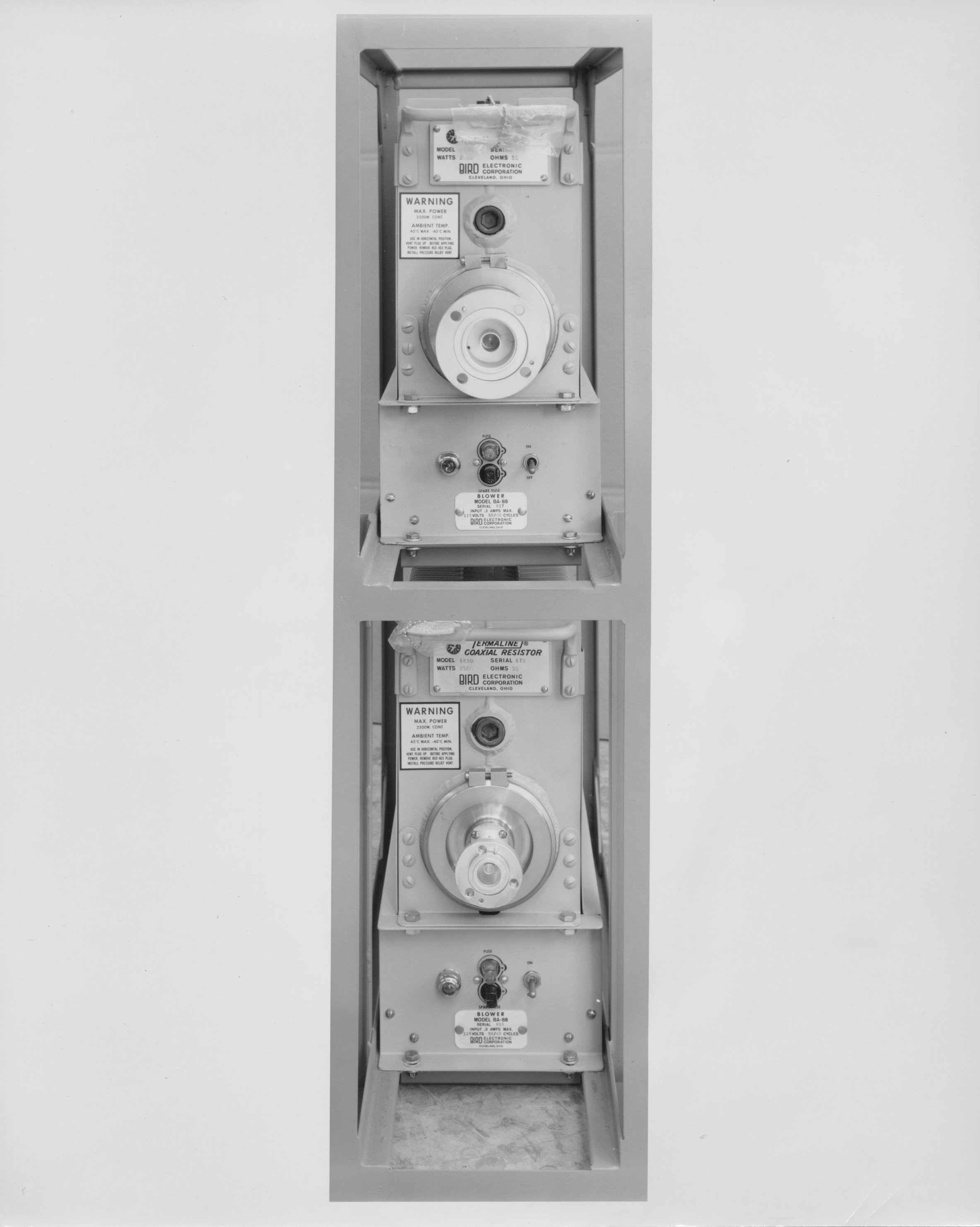
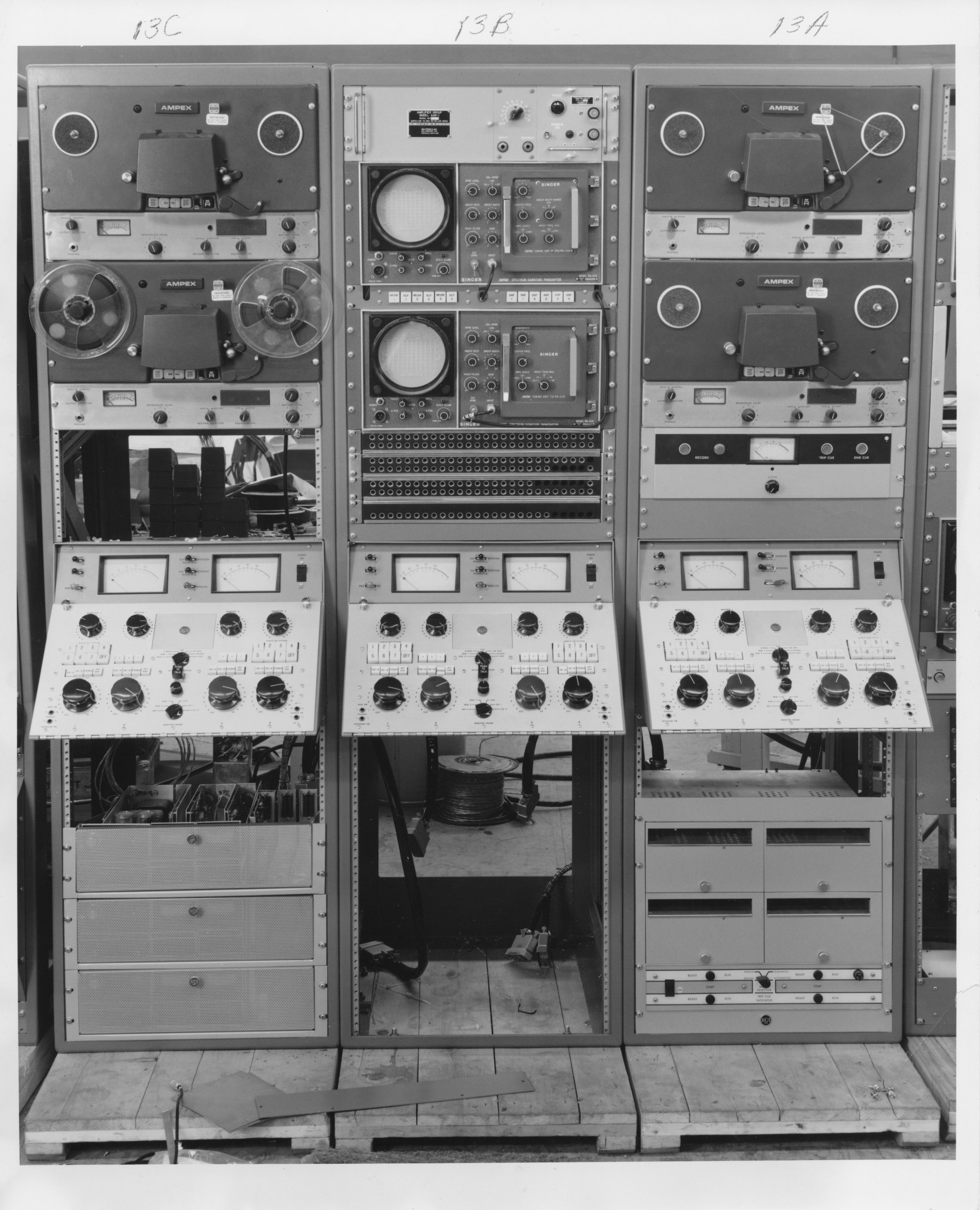
| Unit 12B VHF Dummy Loads | 683.1-7 Unit 12B End View | 681.18-7 Units 13 C, B, A | 681.18-8 Units 13 |
 |
 |
 |
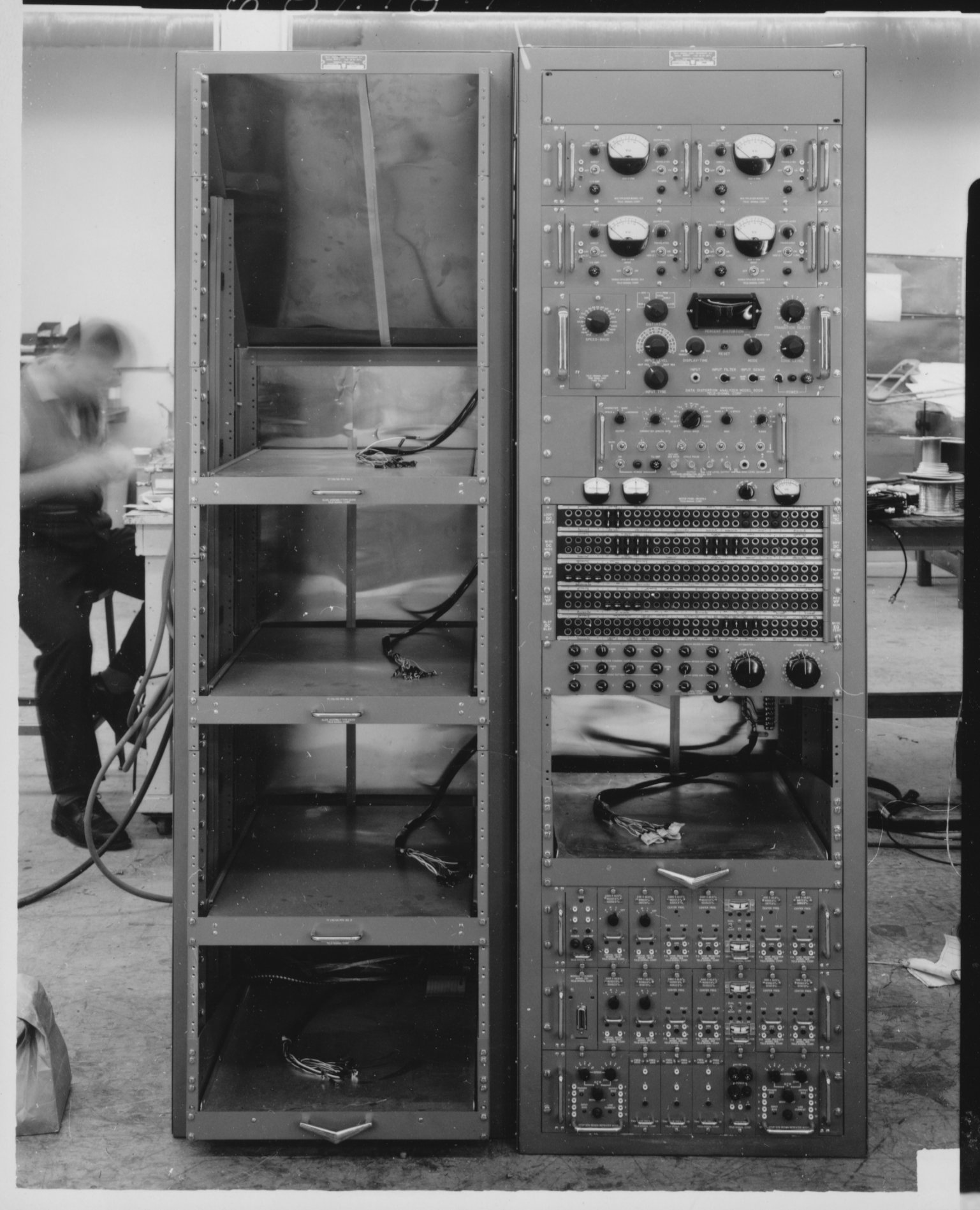 |
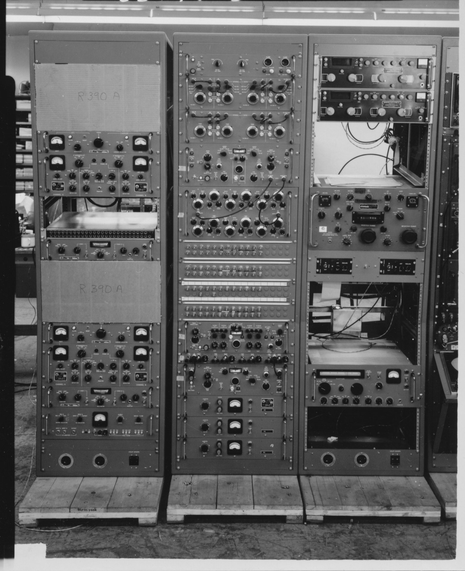
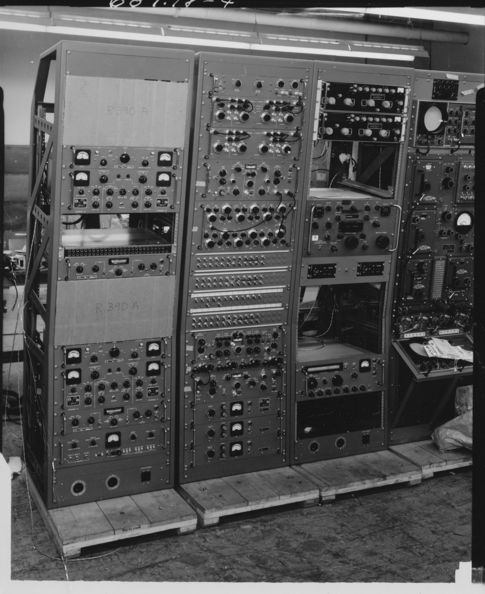
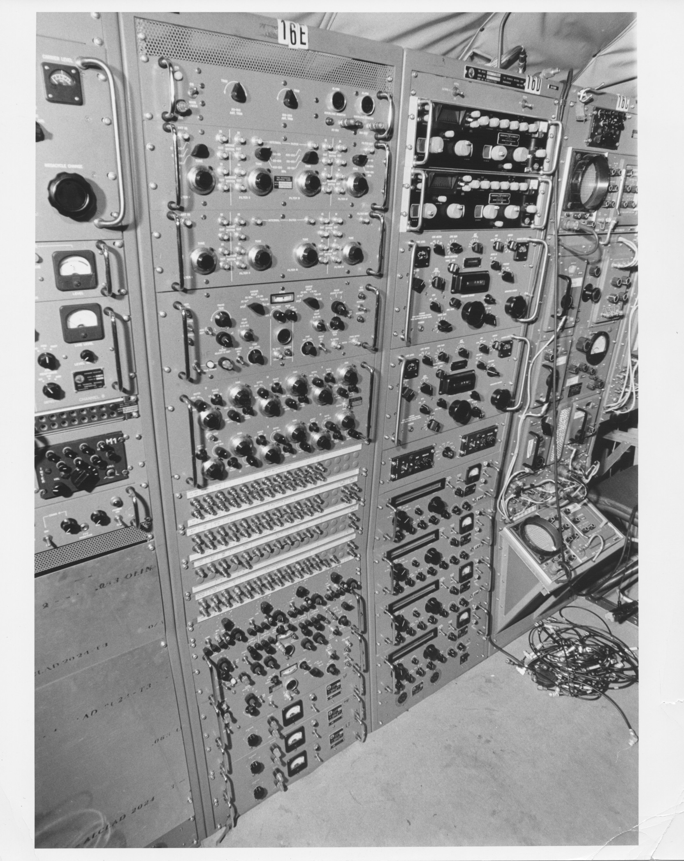
| 685-3.3 Unit 14A (in center of photo) | 681.18-3 Units 14A (left) and 16D,E (right) | 681.18-4 Units 14A (left) and 16D,E (right) | 681.18-1 Units 14 B and C while under construction |
 |
 |
 |
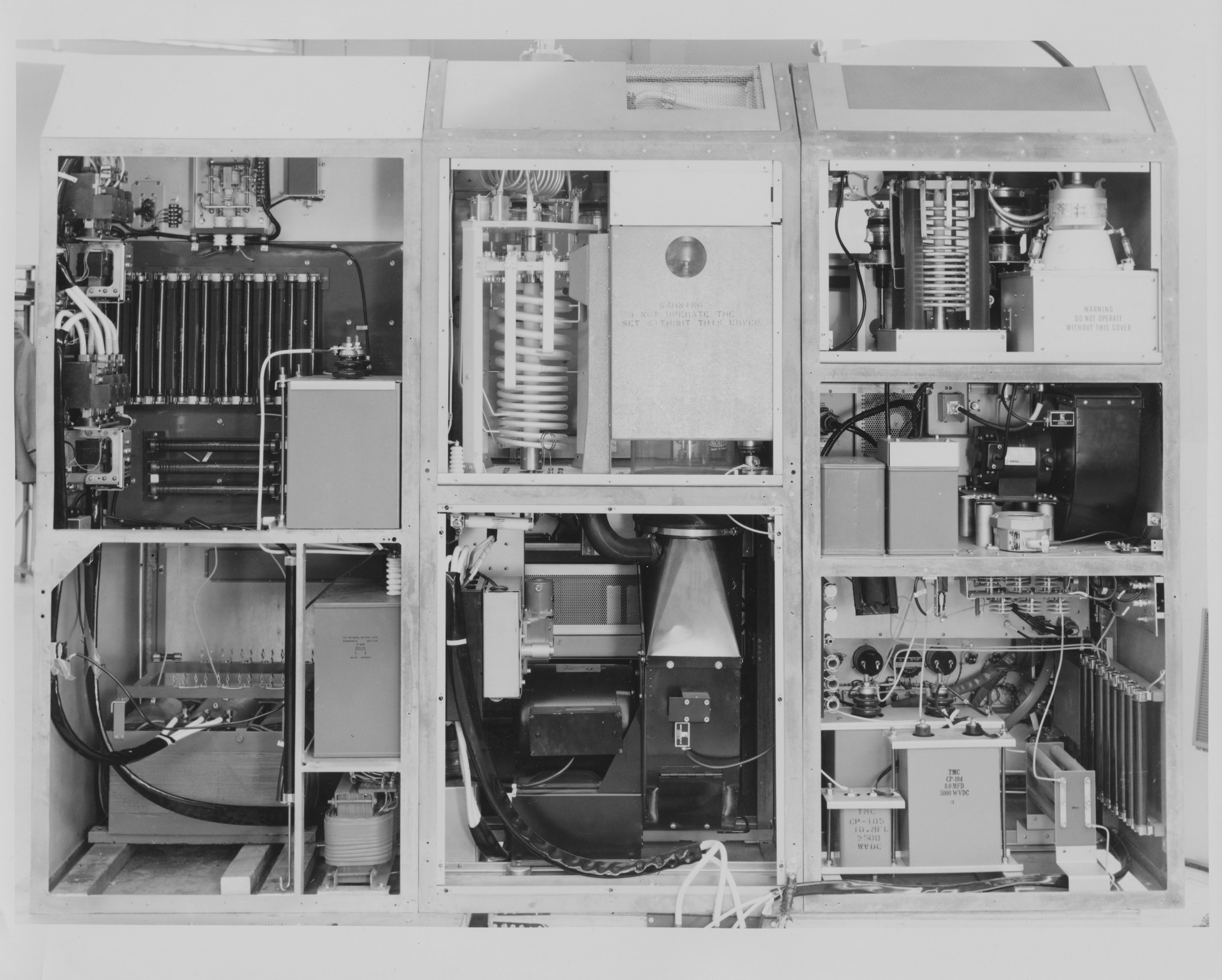 |
| 681.18-2 Units 14B and C | 681.18-6 Units 16 A,B,C These appear to be MIL VHF radios | No number. This photo of Units 16 A,B,C was used in the 1968 Annual Report under "Avionics Installations" | 681.29-8. I believe this is the rear view of the GPT-10K modified for use in the Jenny Project. Note the sloping top panels. Also, the photo was stuck in a folder labeled "Blue Eagle". |
 |
 |
 |
 |
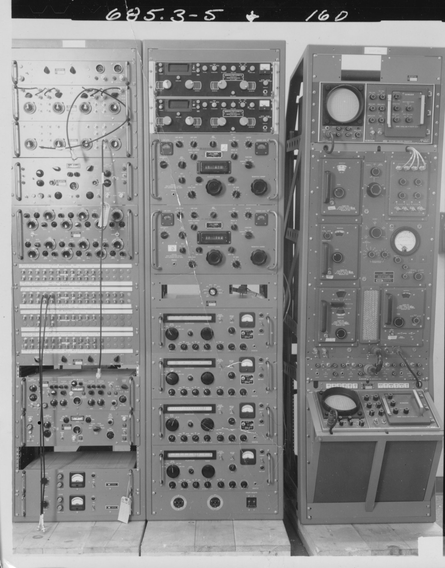
| 683.7-2 Unit 17 front view at TMC plant. | 683.7-1 Yet another view of unit 11. | 685.3-5. Units 16d, 16e, and 16a. | 685.3-6. Units 16d, 16e, and 16a. |
 |
 |
 |
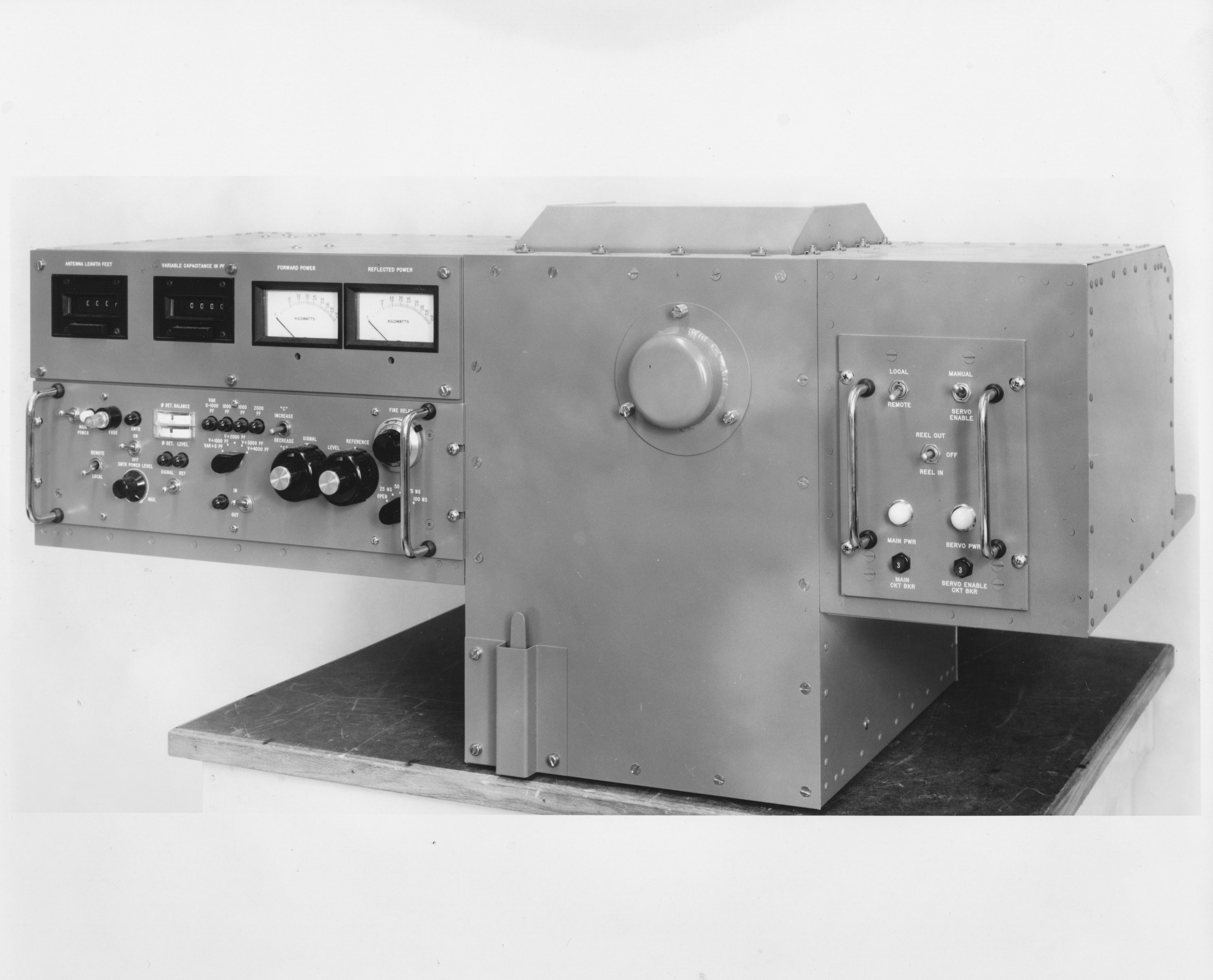 |
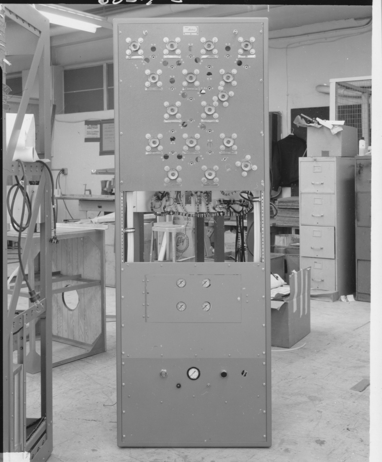
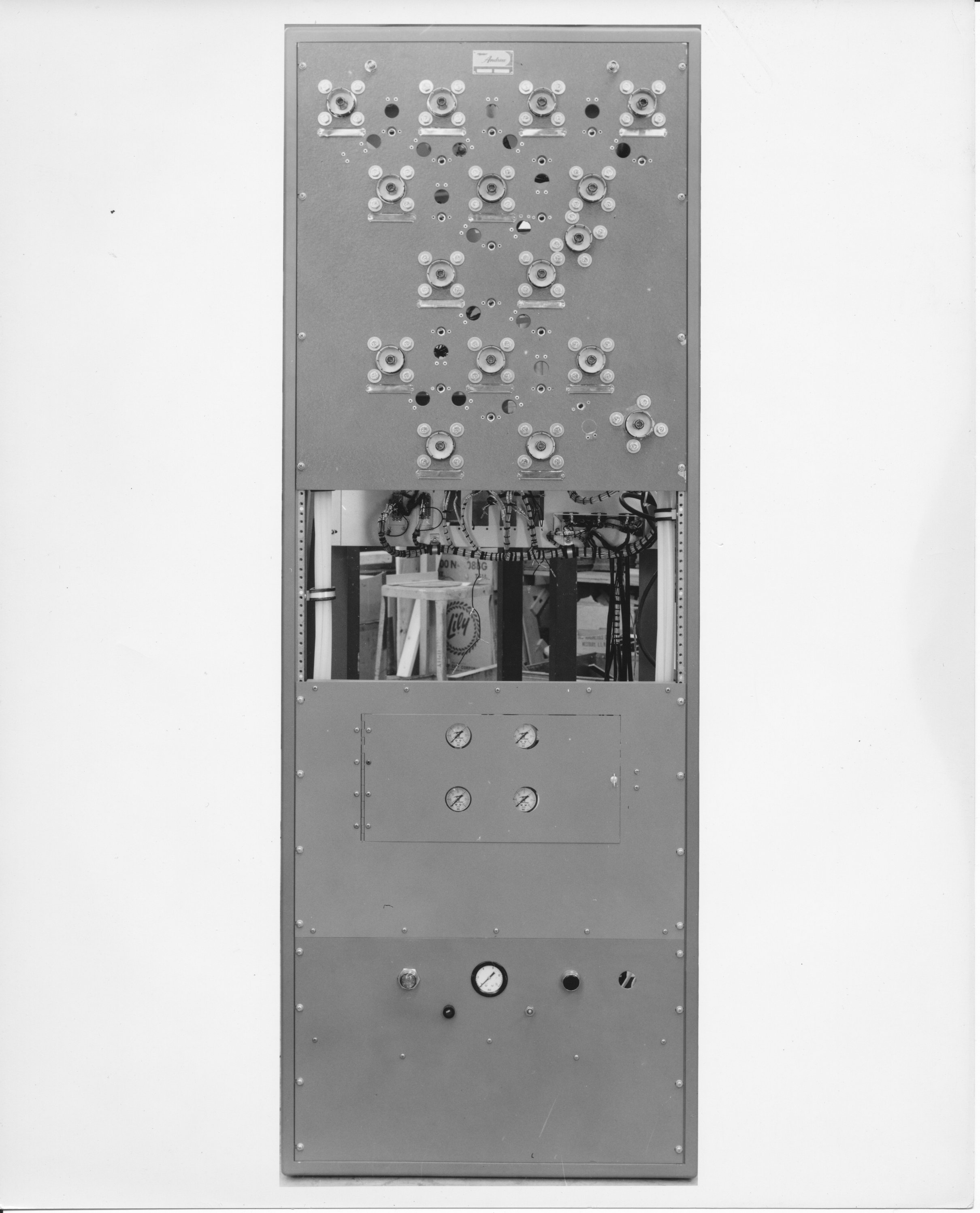
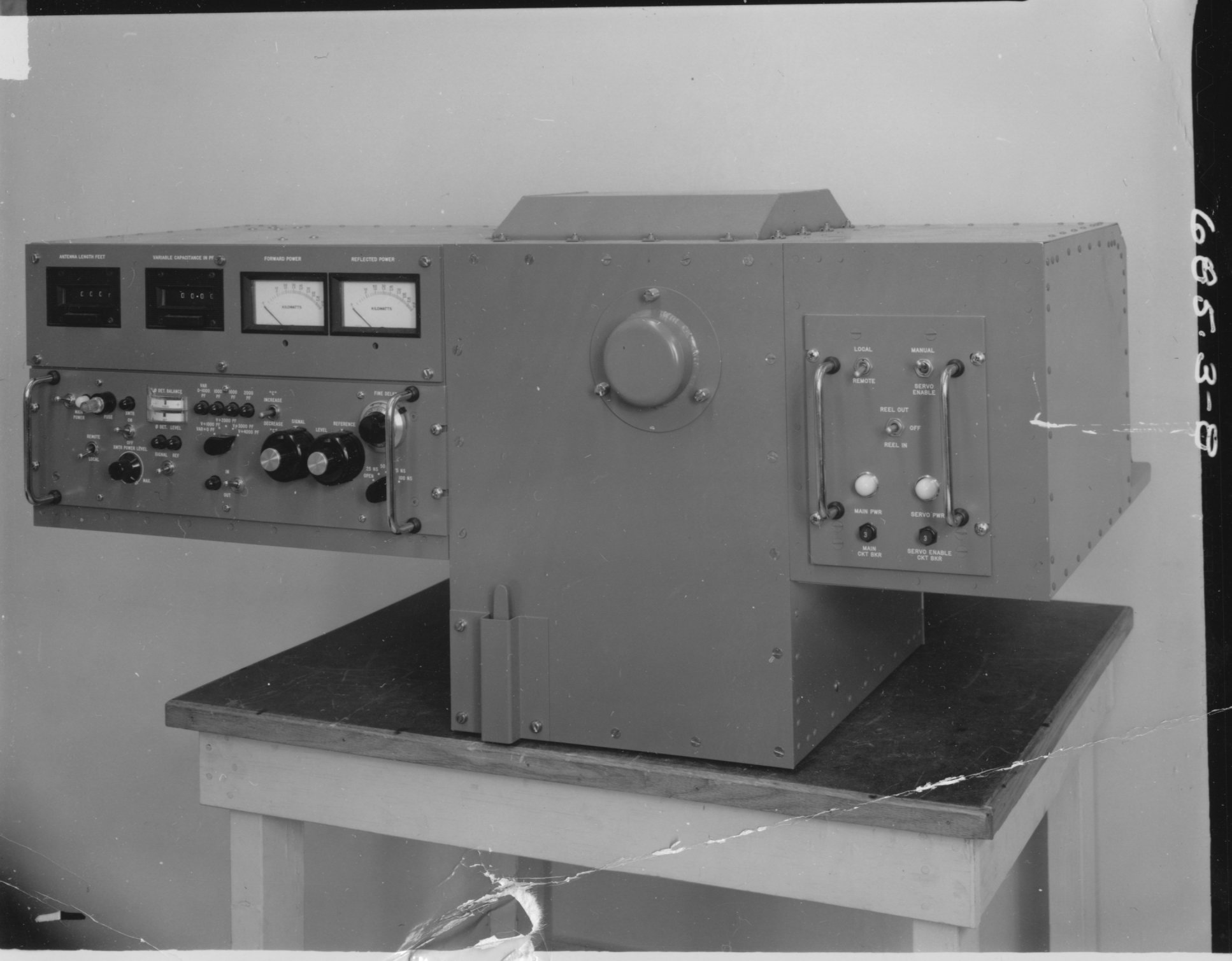
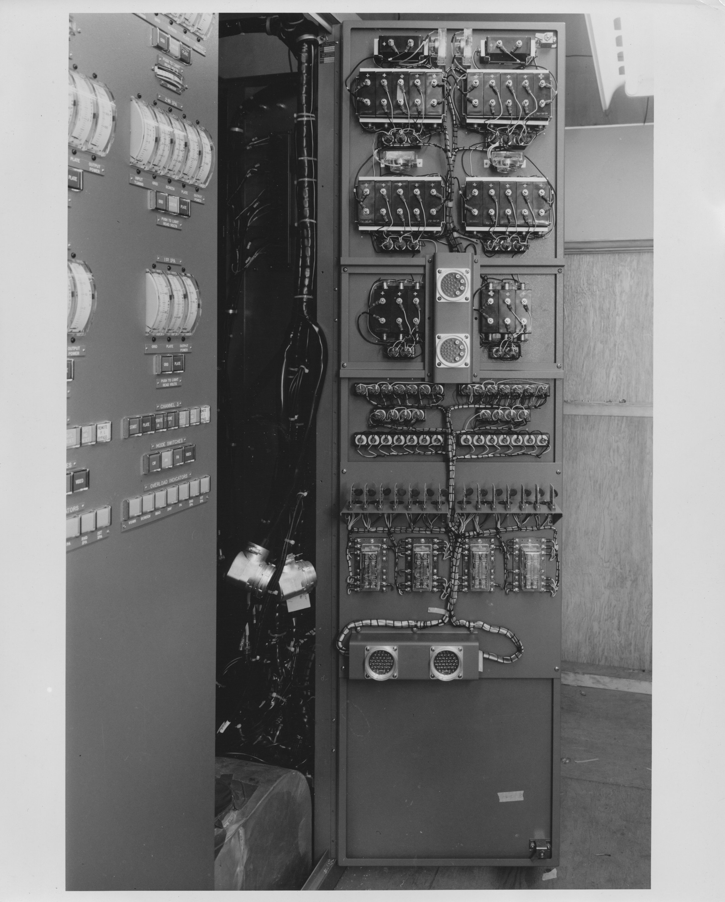
| 685.3-1 Unit 17 | 681.18-10 Unit 17 | 686.5-1 Unit (unknown) | 685.3-8 Back of photo says "5", but is hard to read. This unit appears to be the VLF antenna tuner and trailing-wire antenna winch. |
 |
 |
 |
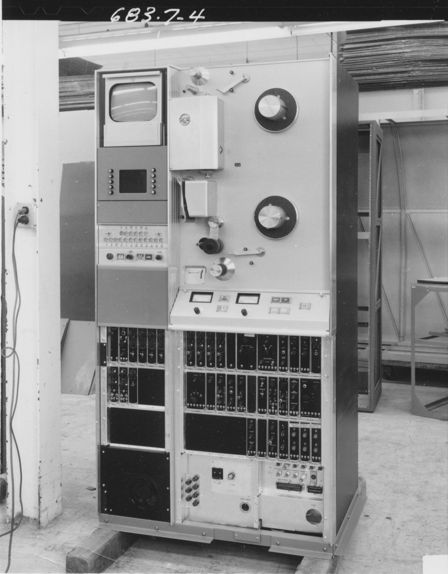 |
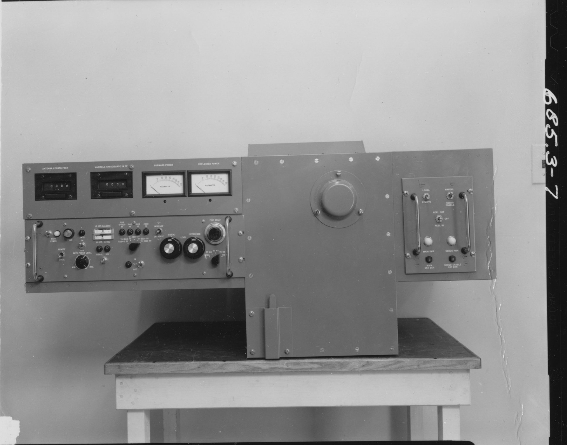
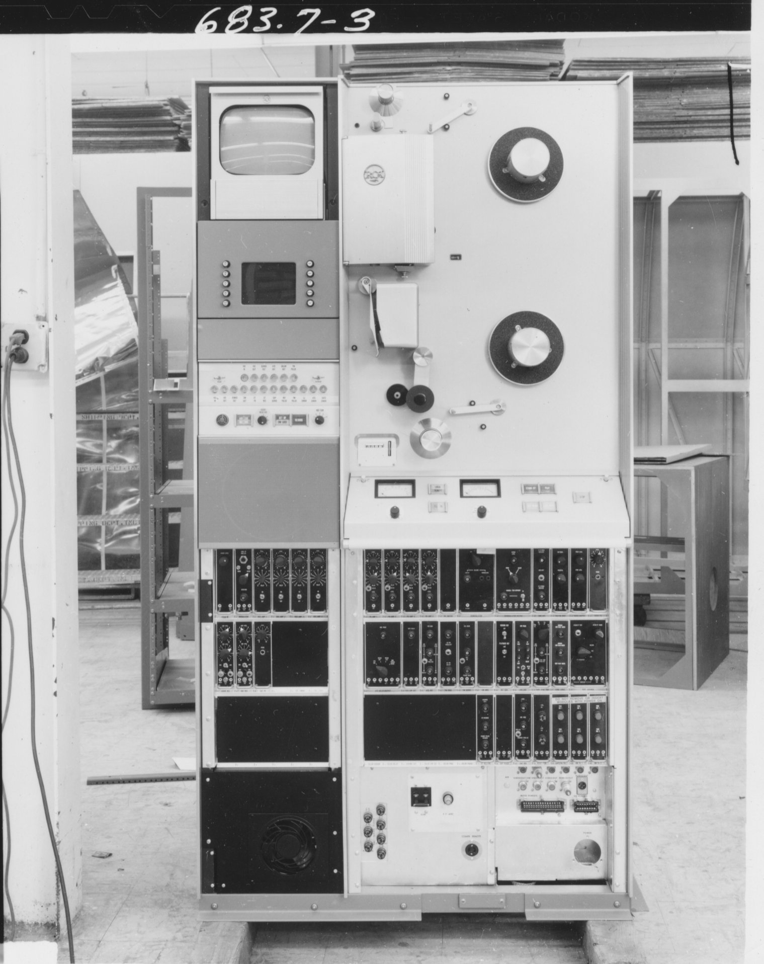
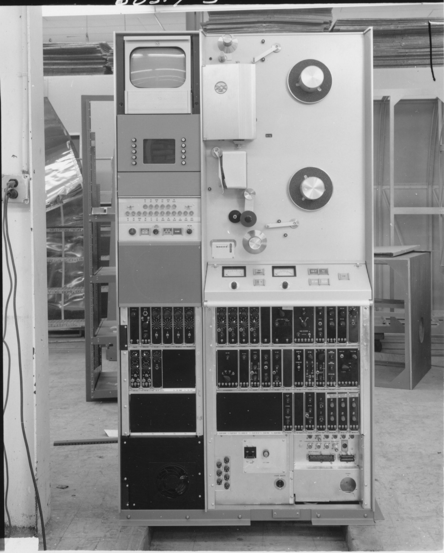
| 685.3-7. Another view of the tuner/reel. | 685.3-8. Antenna tuner/reel. | 683.7-3. VTR front view. | 683.7-4 VTR front/right view. |
 |
 |
 |
 |
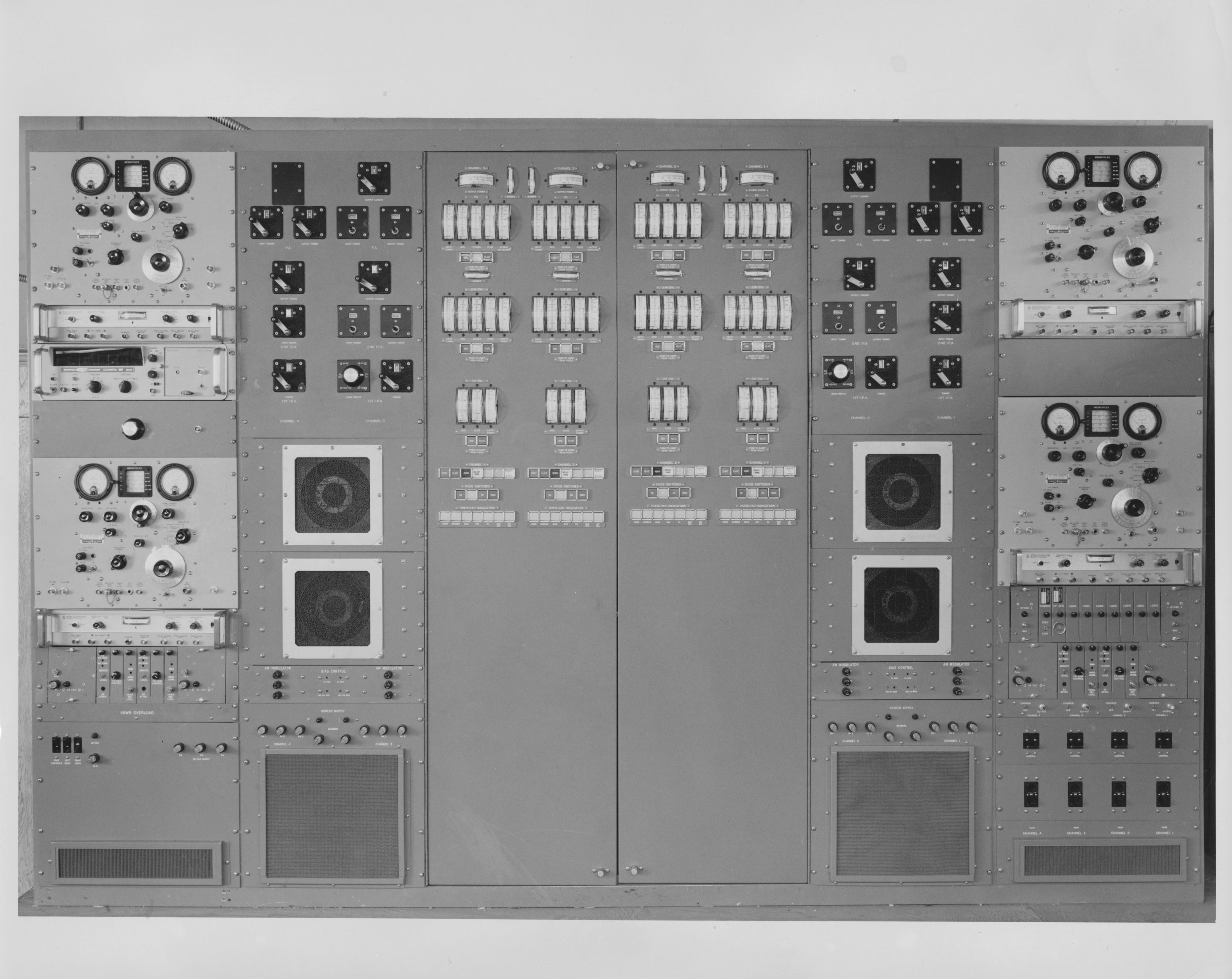
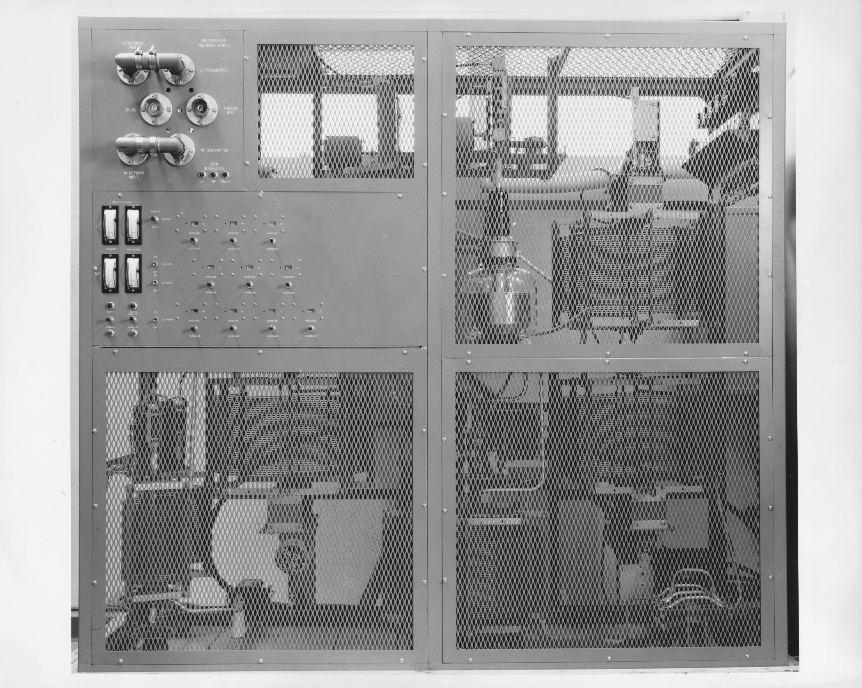
| 6811.5-1 TMC SPT-3KVHF Transmitter. This unit provided CW, AM, FM, and television transmission between 30 and 350 Mc. Evidently, it could provide 4 simultaneous 2KW outputs in pairs on two bands. This transmitter was designed and built by Multronics, Inc, under contract to TMC. | No photo number, but clearly the SPT-3KVHF shown in 6811.5-1 while under construction. | 6811.5-2. Overall view of SPT-3KVHF transmitter. | 687.5-5 View behind one of the two switching panels of the SPB-3KVHF. |
 |
 |
 |
 |
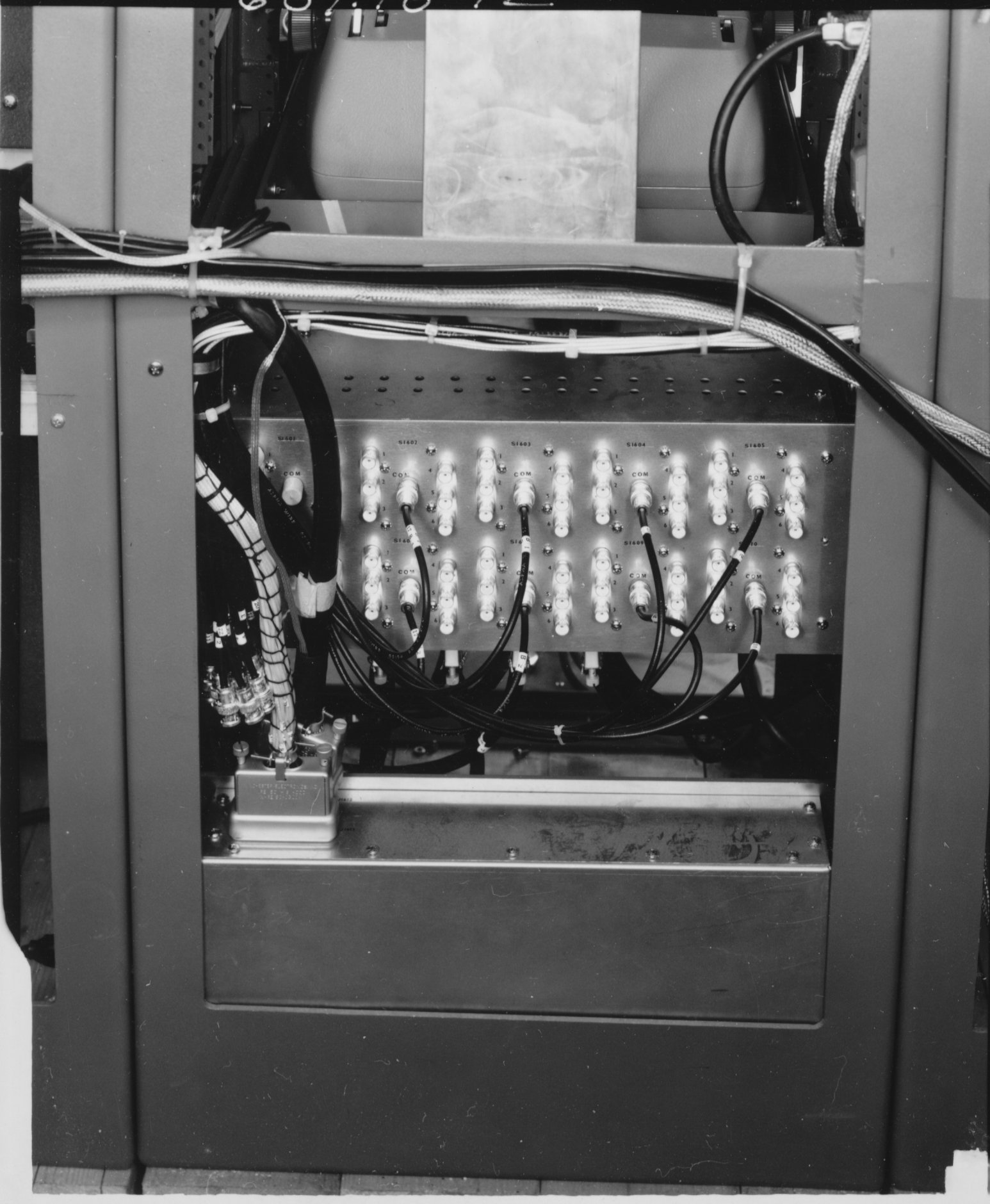
| 681.18-11 16 Rear | 681.18-12 16 Rear | 686.5-4 Unit 3. This is the ATMC transmitter multicoupler that allows an MF and an LF transmitter to operate simultaneously over the trailing wire antenna. The unit was designed an built by Multronics under contract to TMC. | 683.7-3 Video Tape Player |
 |
 |
 |
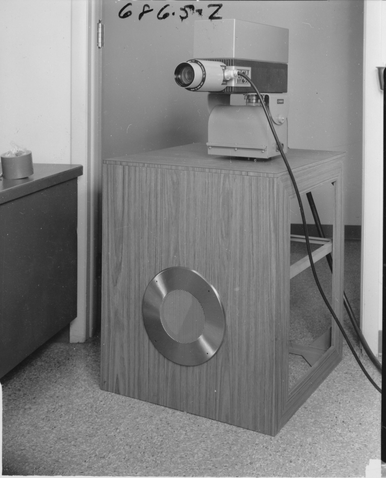 |
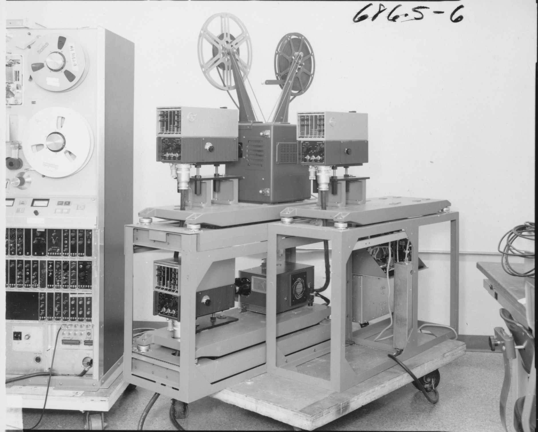
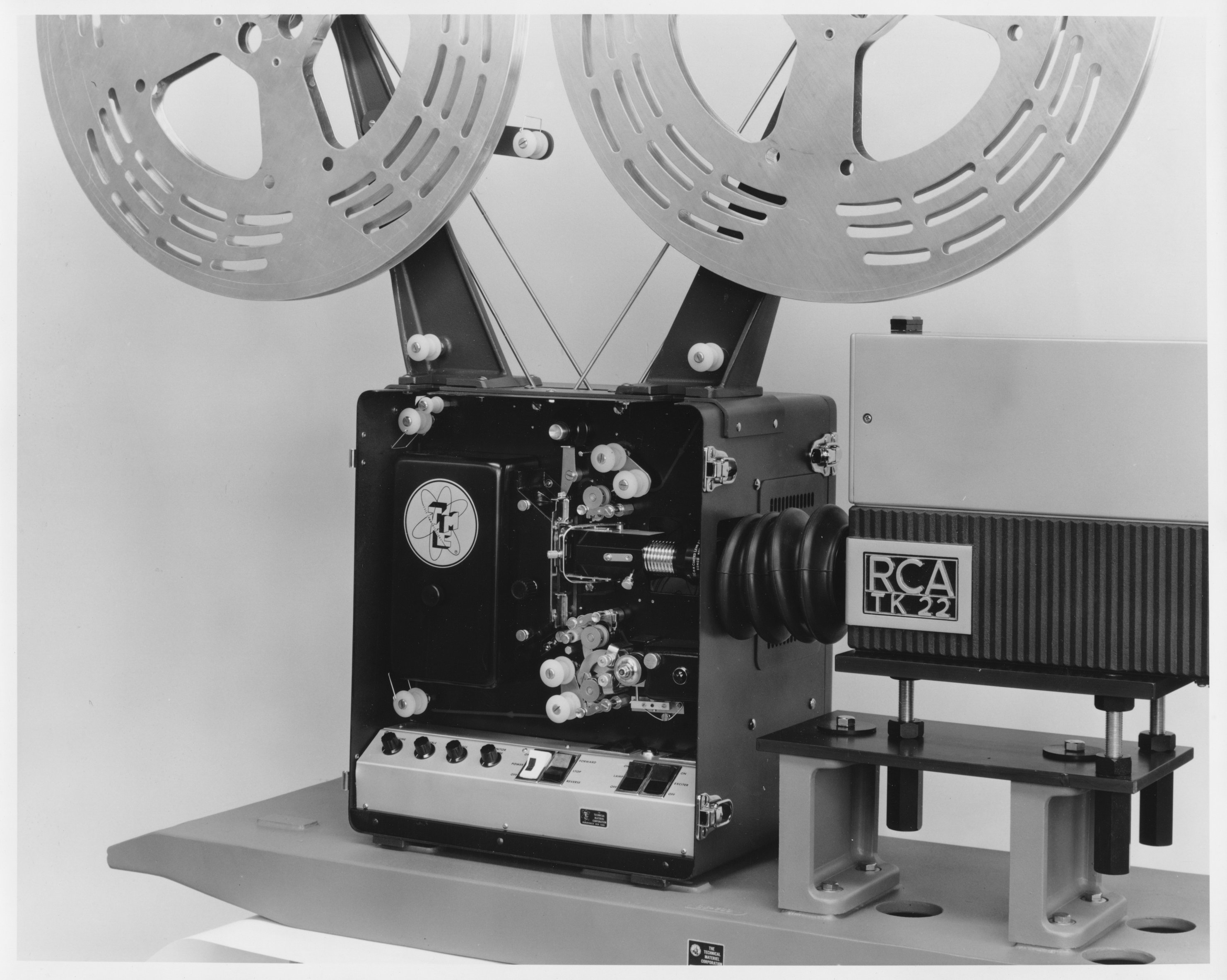
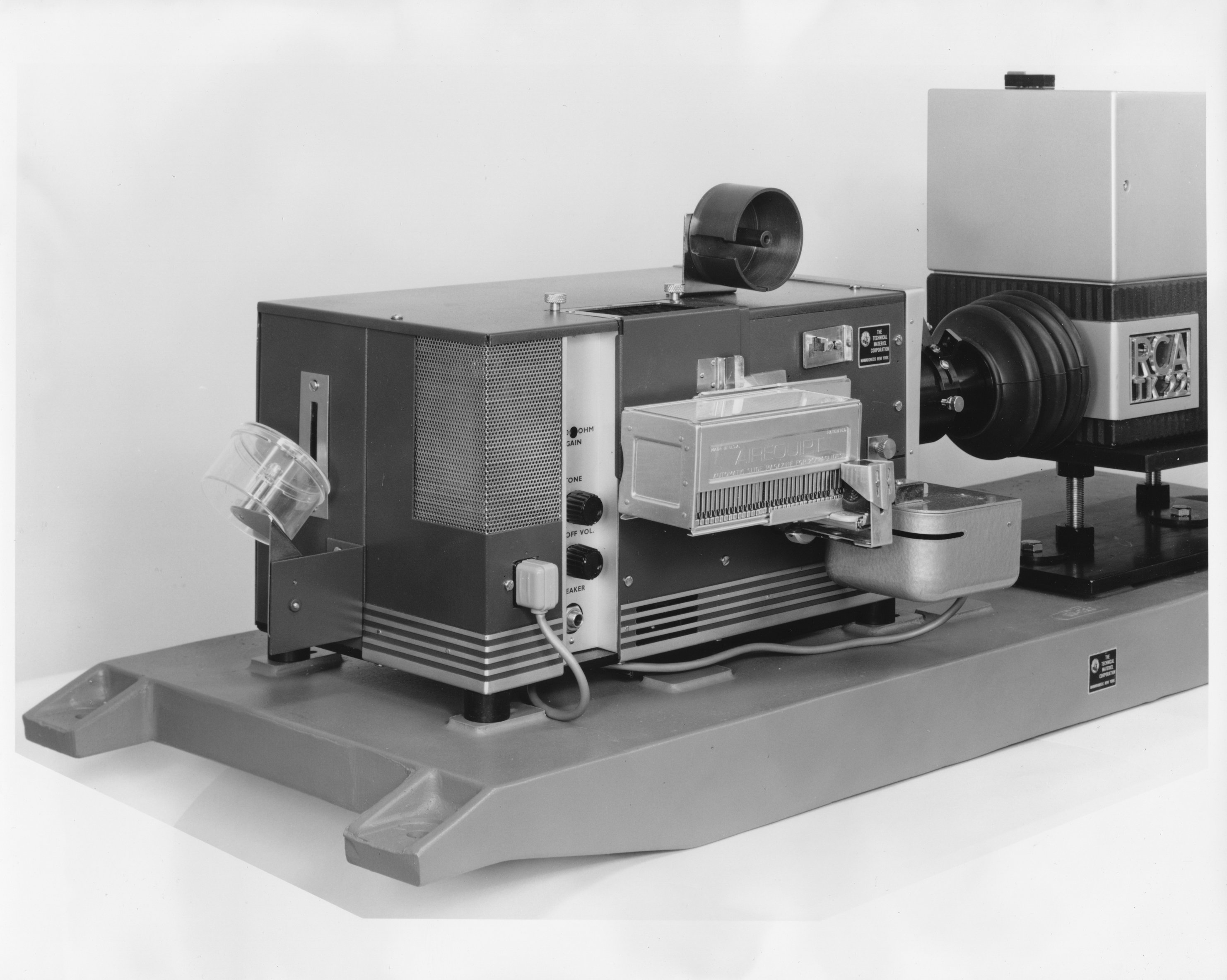
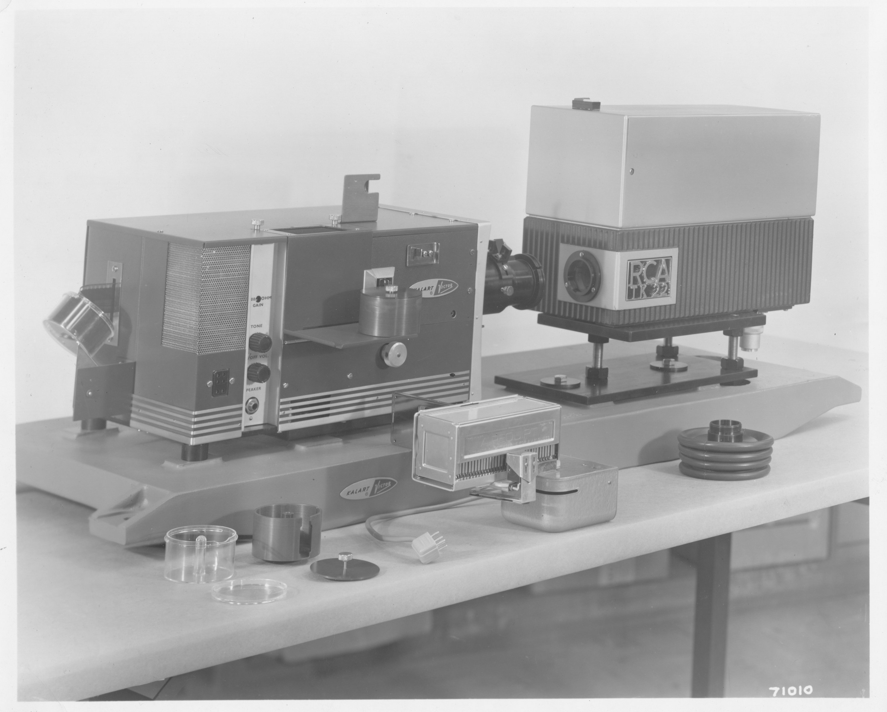
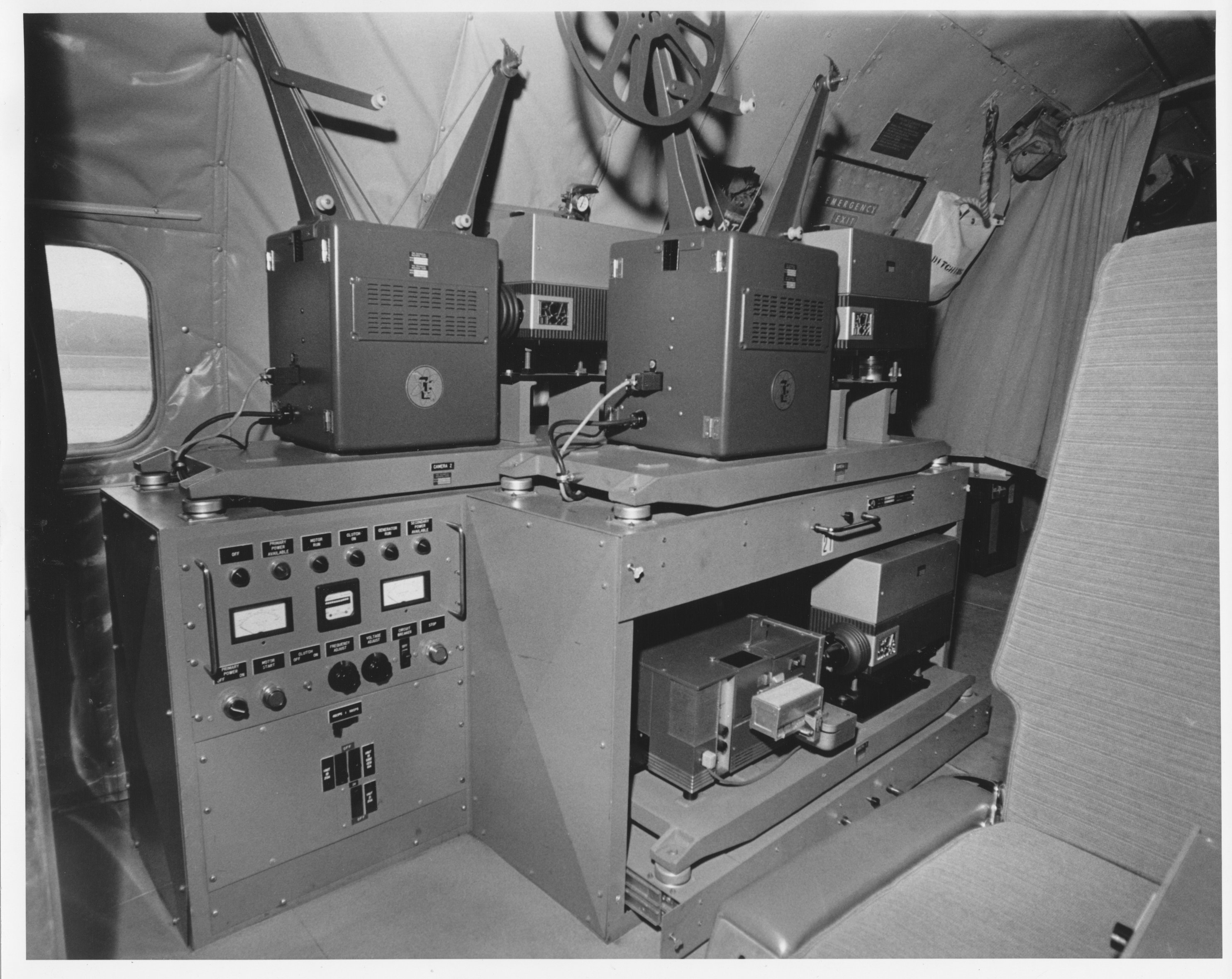
| 686.5-6 Kinescope equipment, also referred to as "camera chain" Bottom camer is attached to a slide projector. | No photo number, but both of these photos in folder titled "Camera Chain" | 686.5-2 TV camera, not clear what purpose.. see below in aircraft interior photos | |
 |
 |
 |
 |
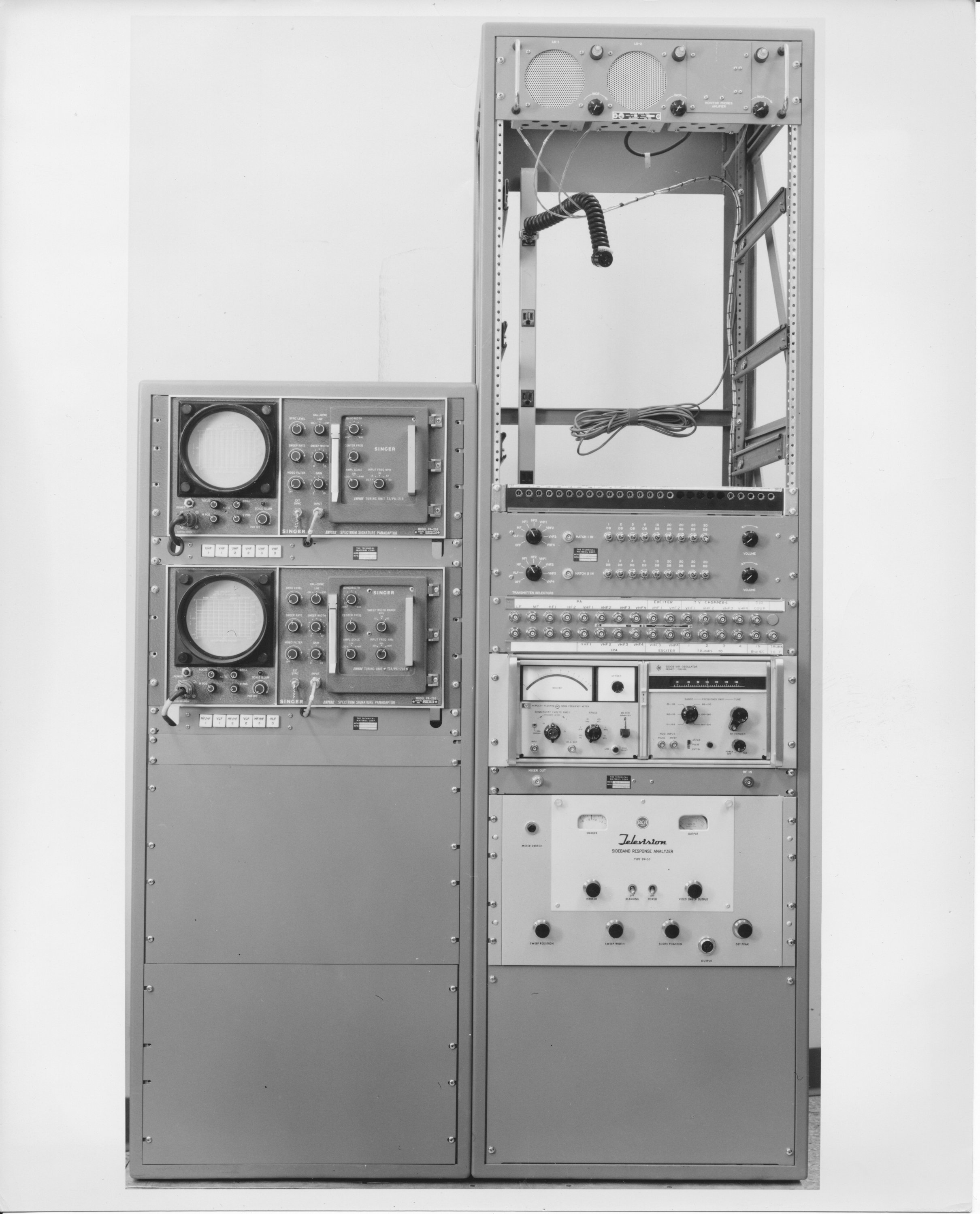
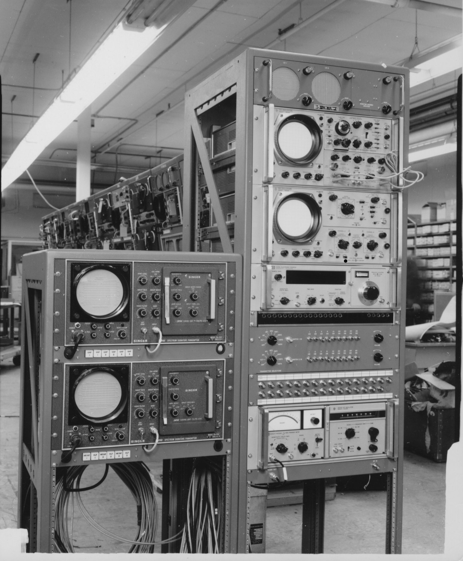
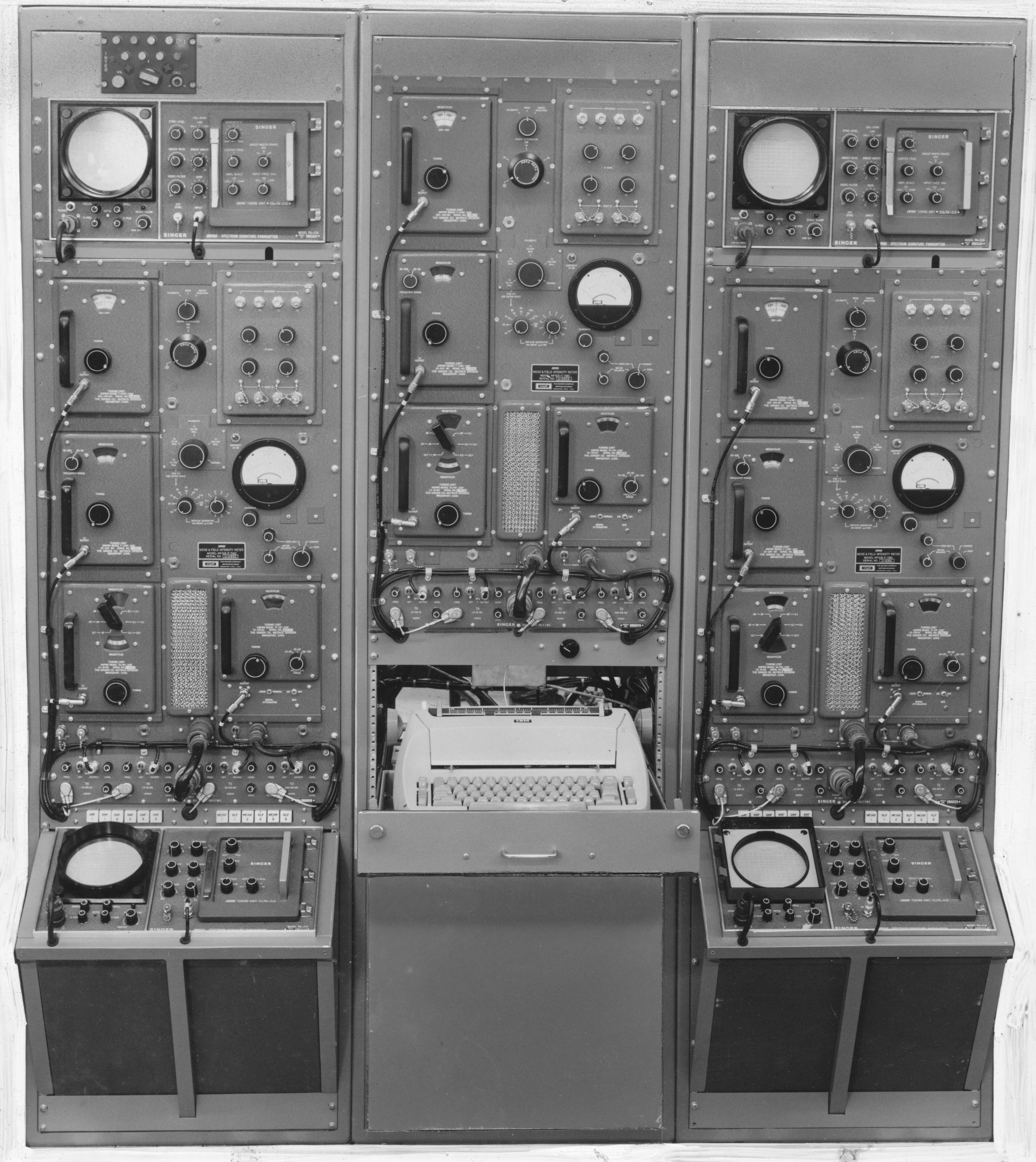
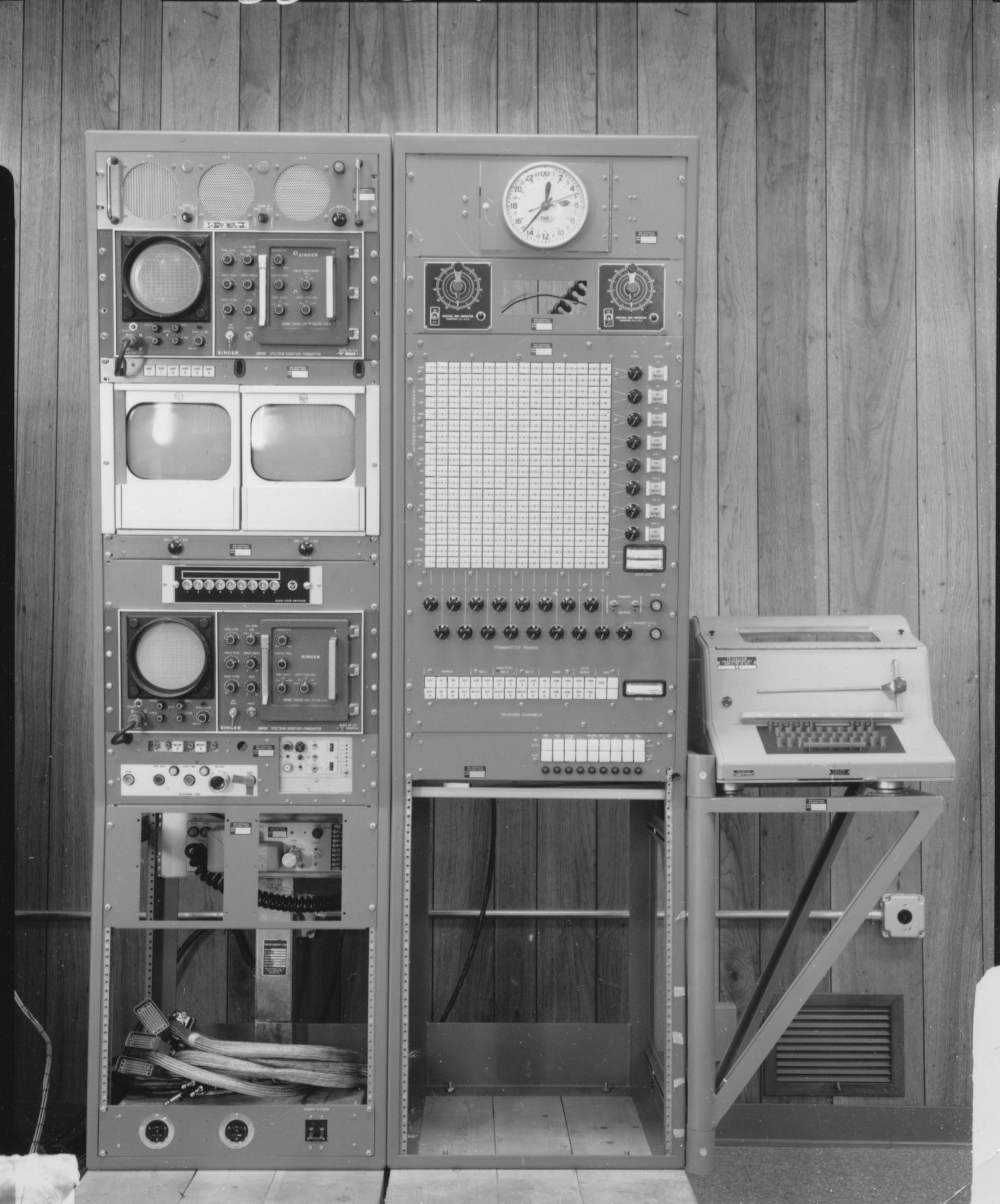
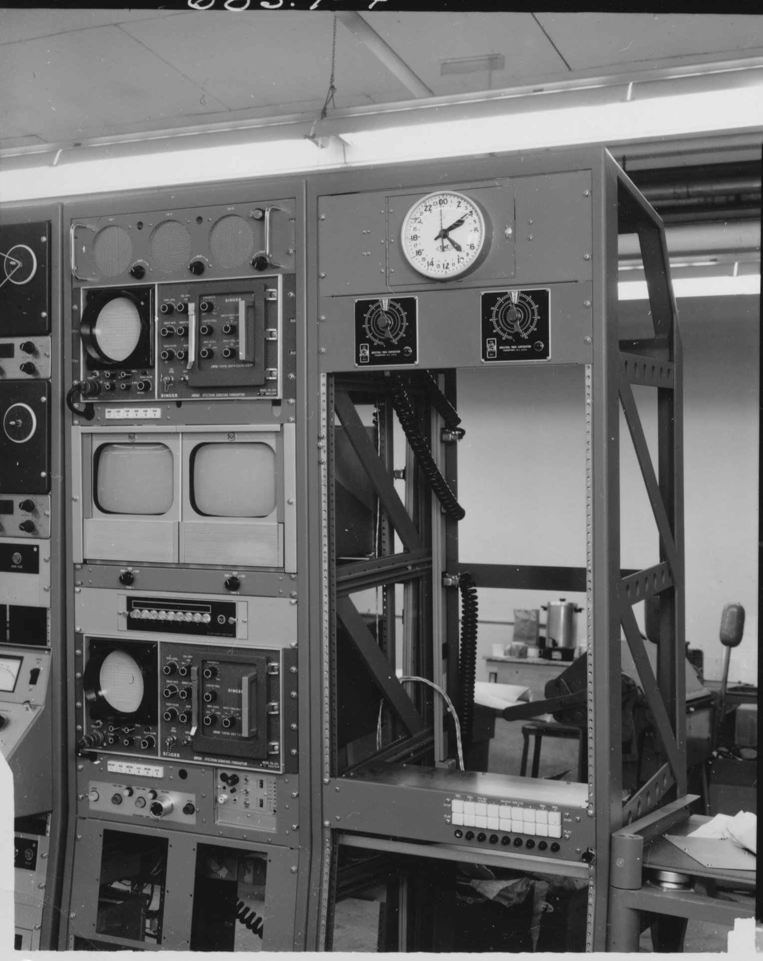
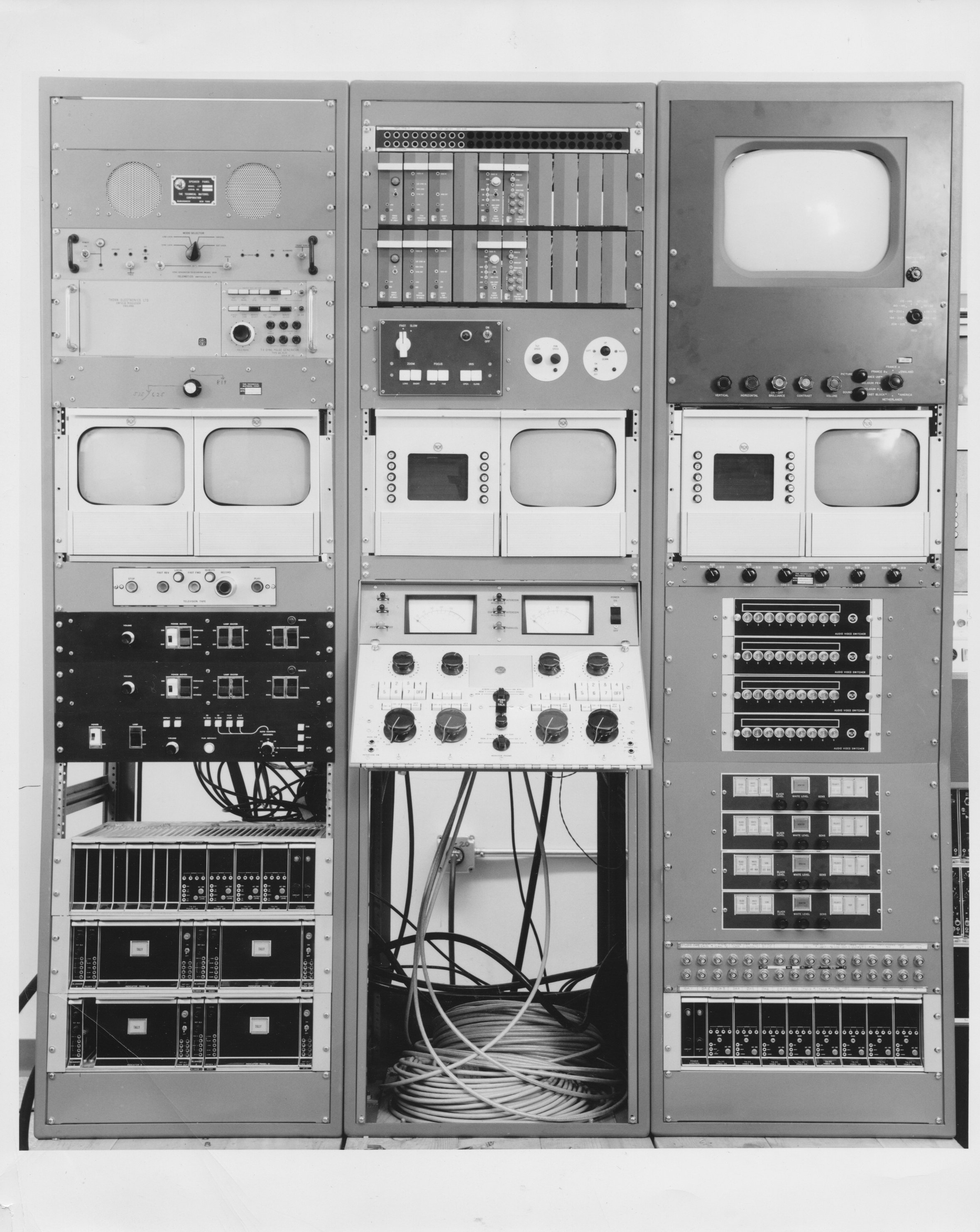
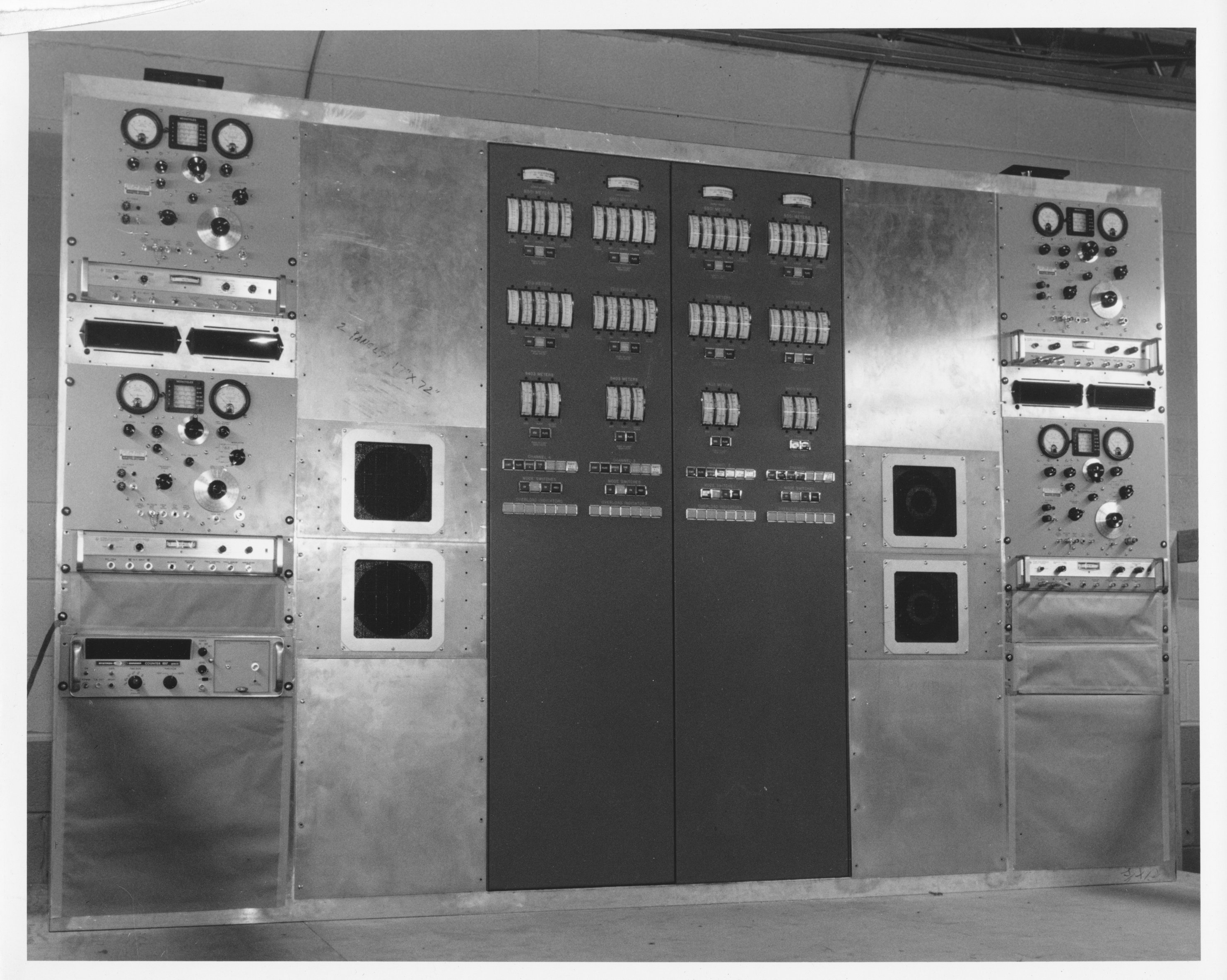
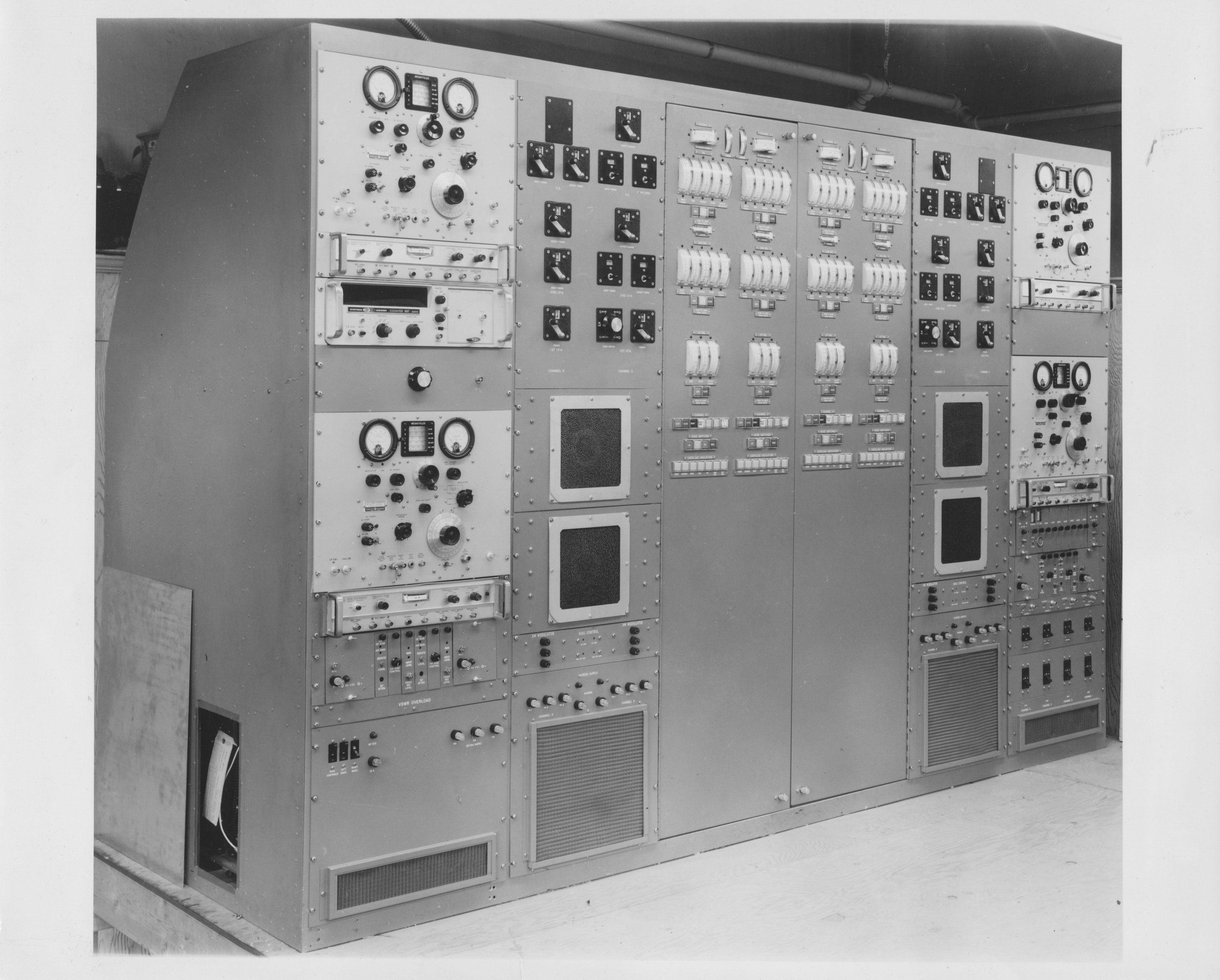
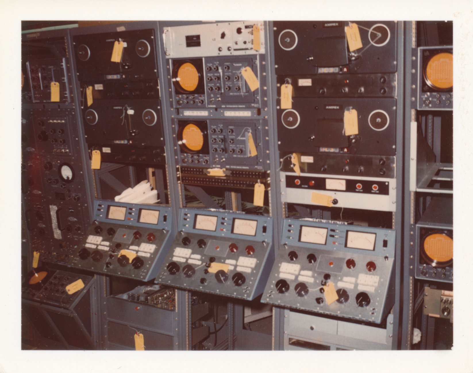
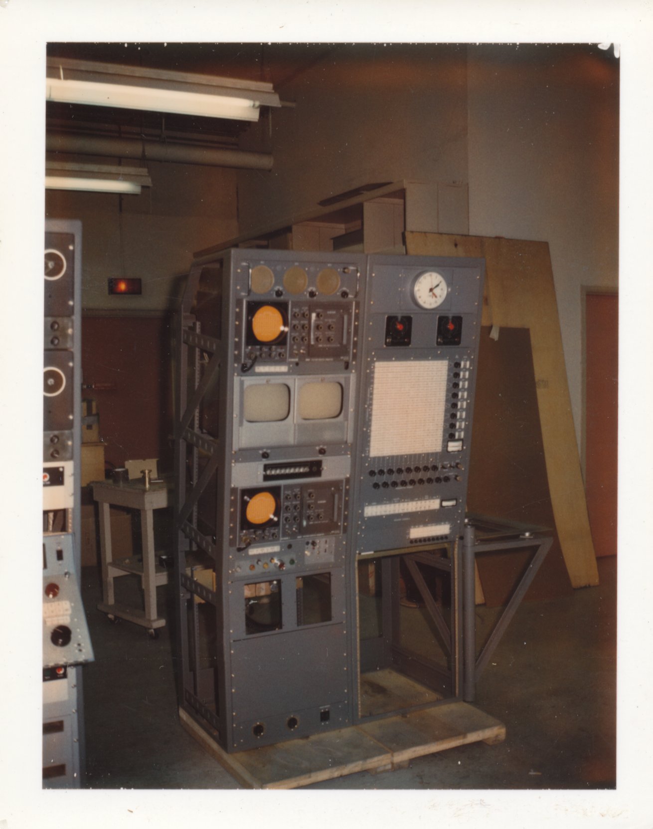
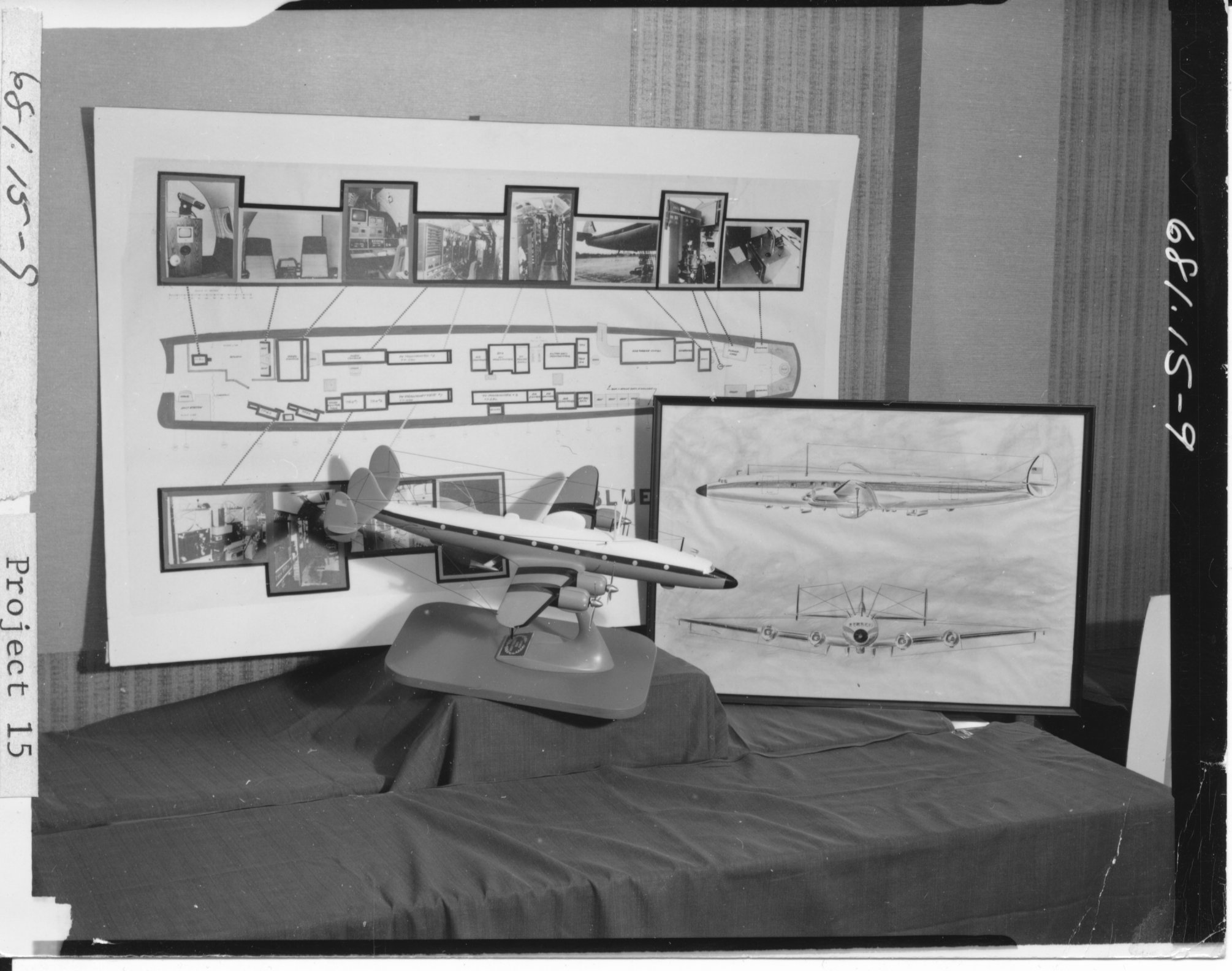
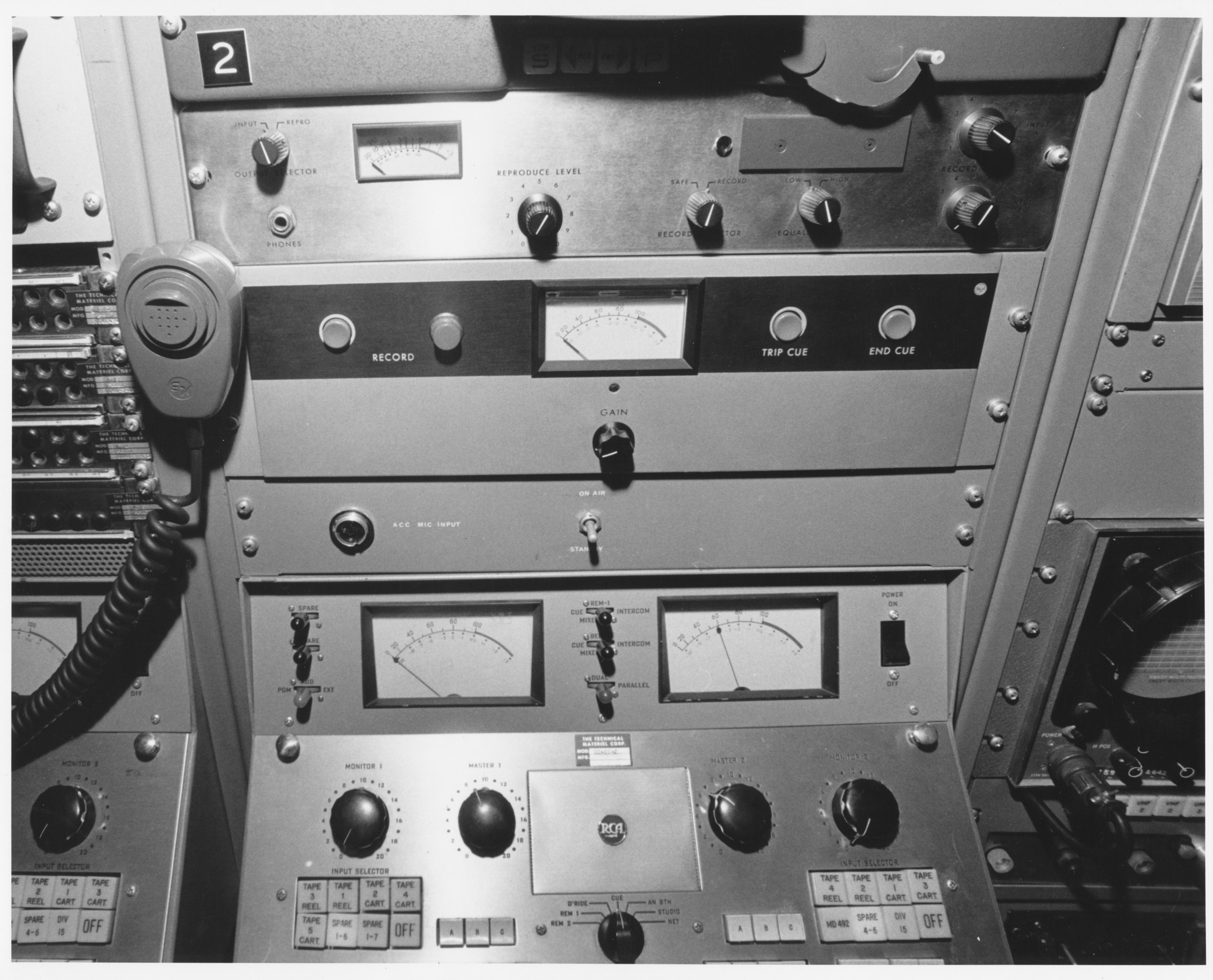
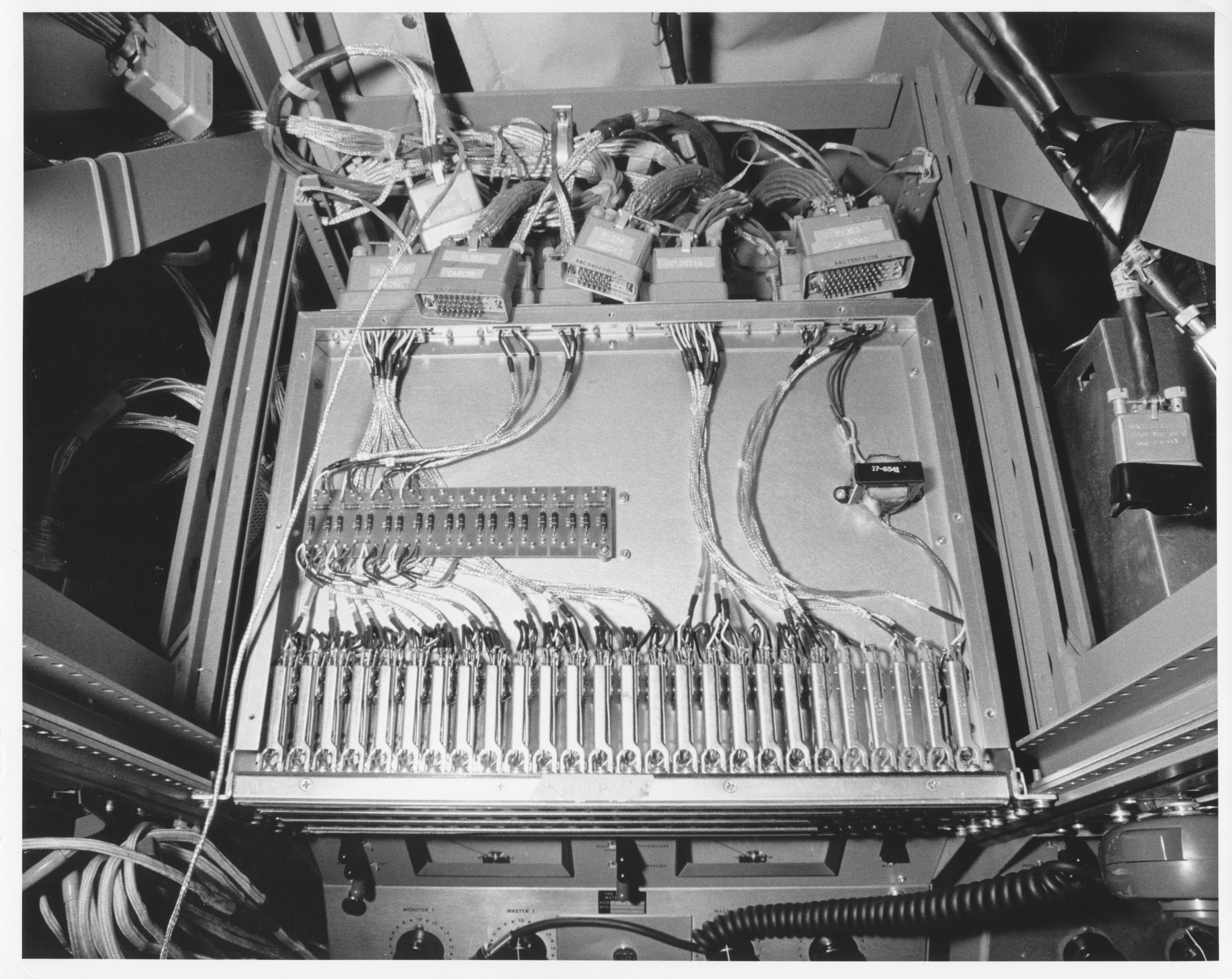
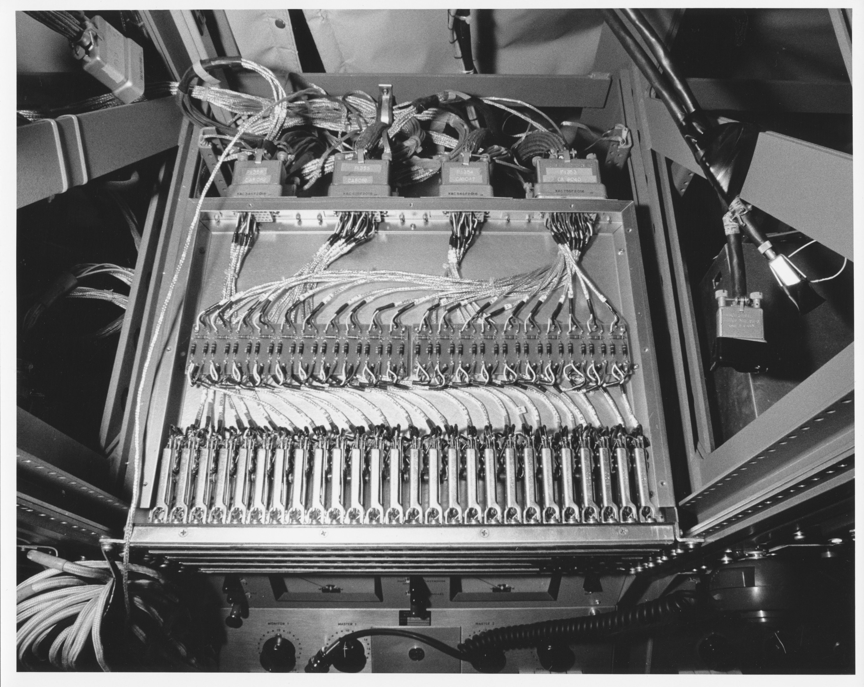
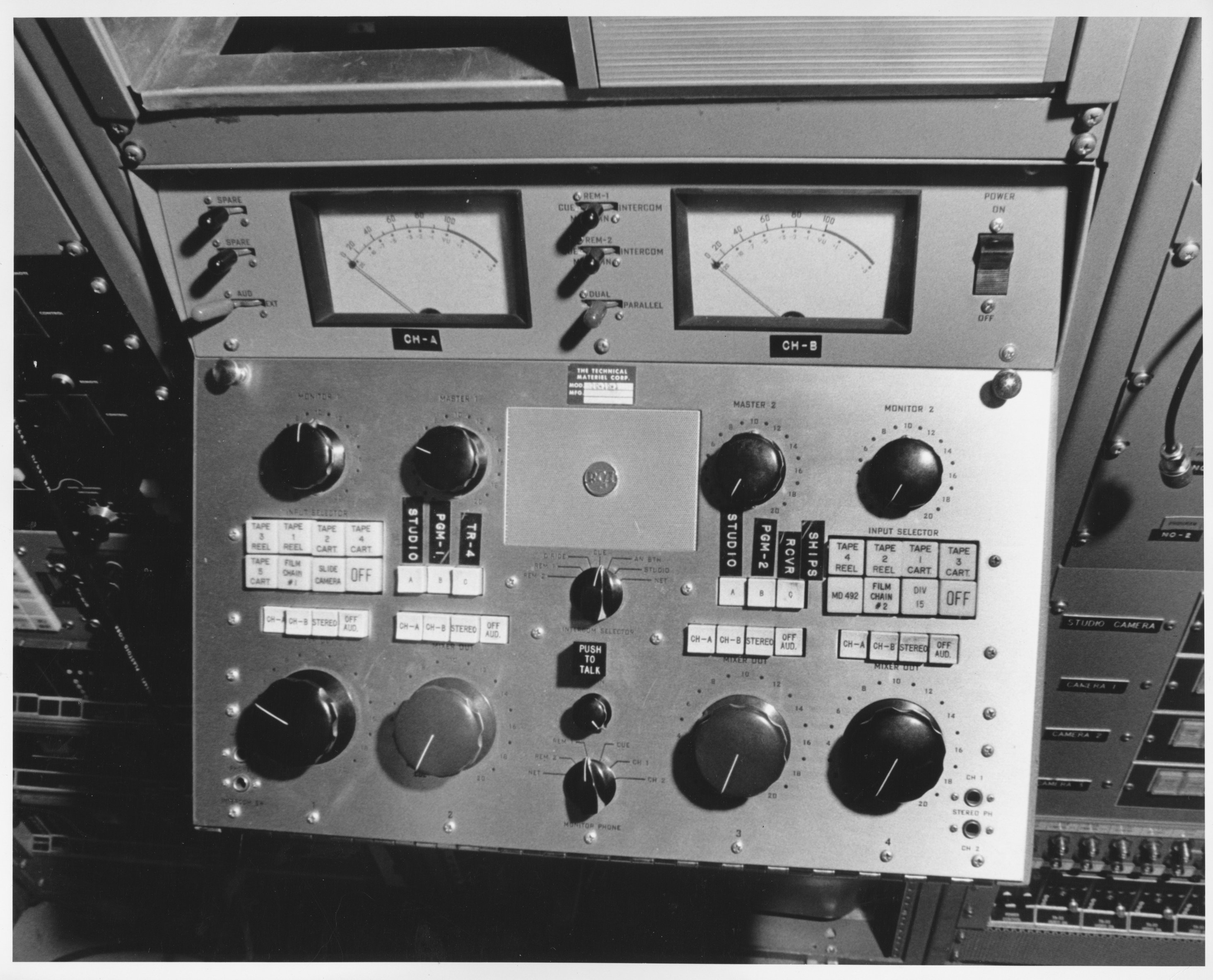
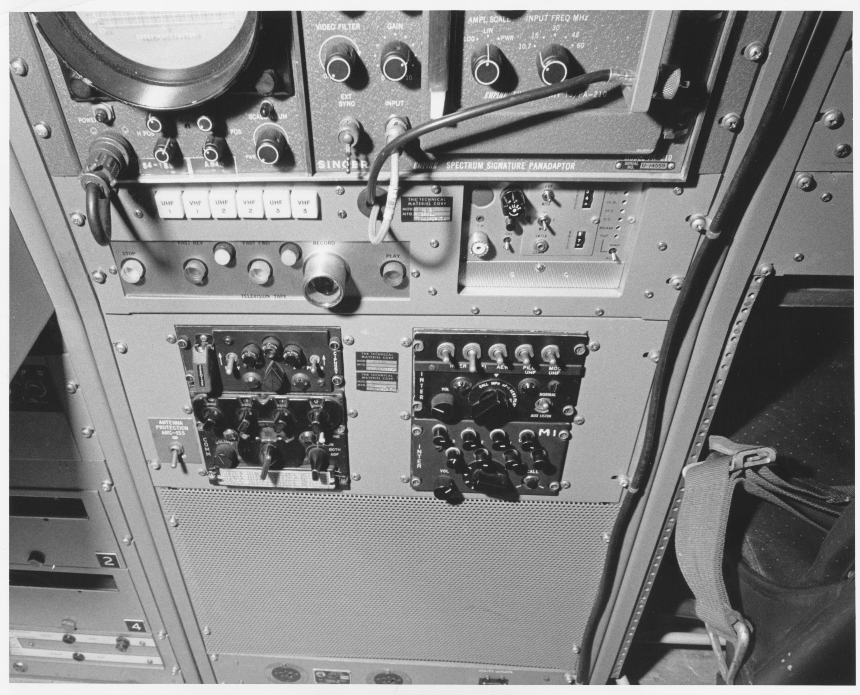
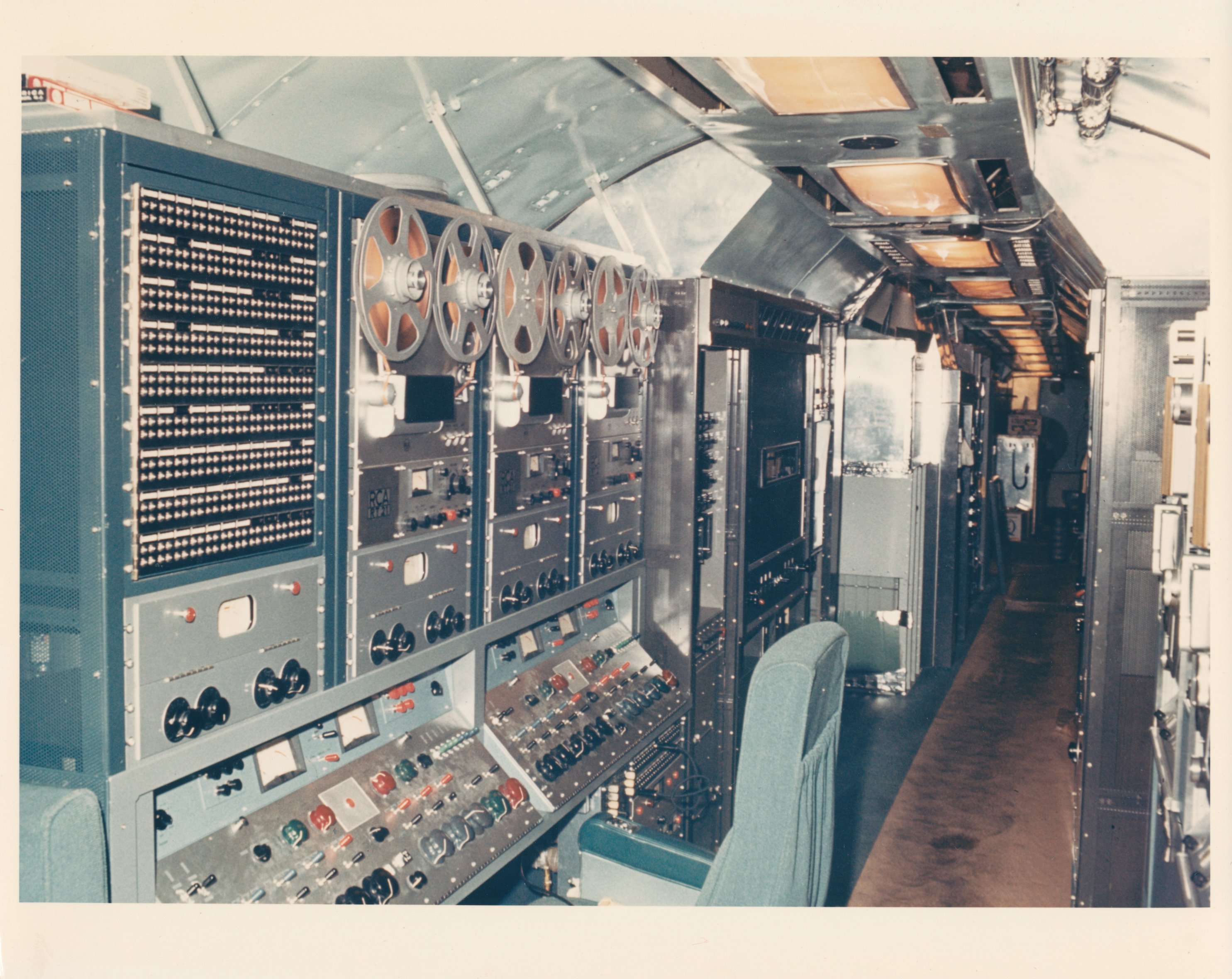
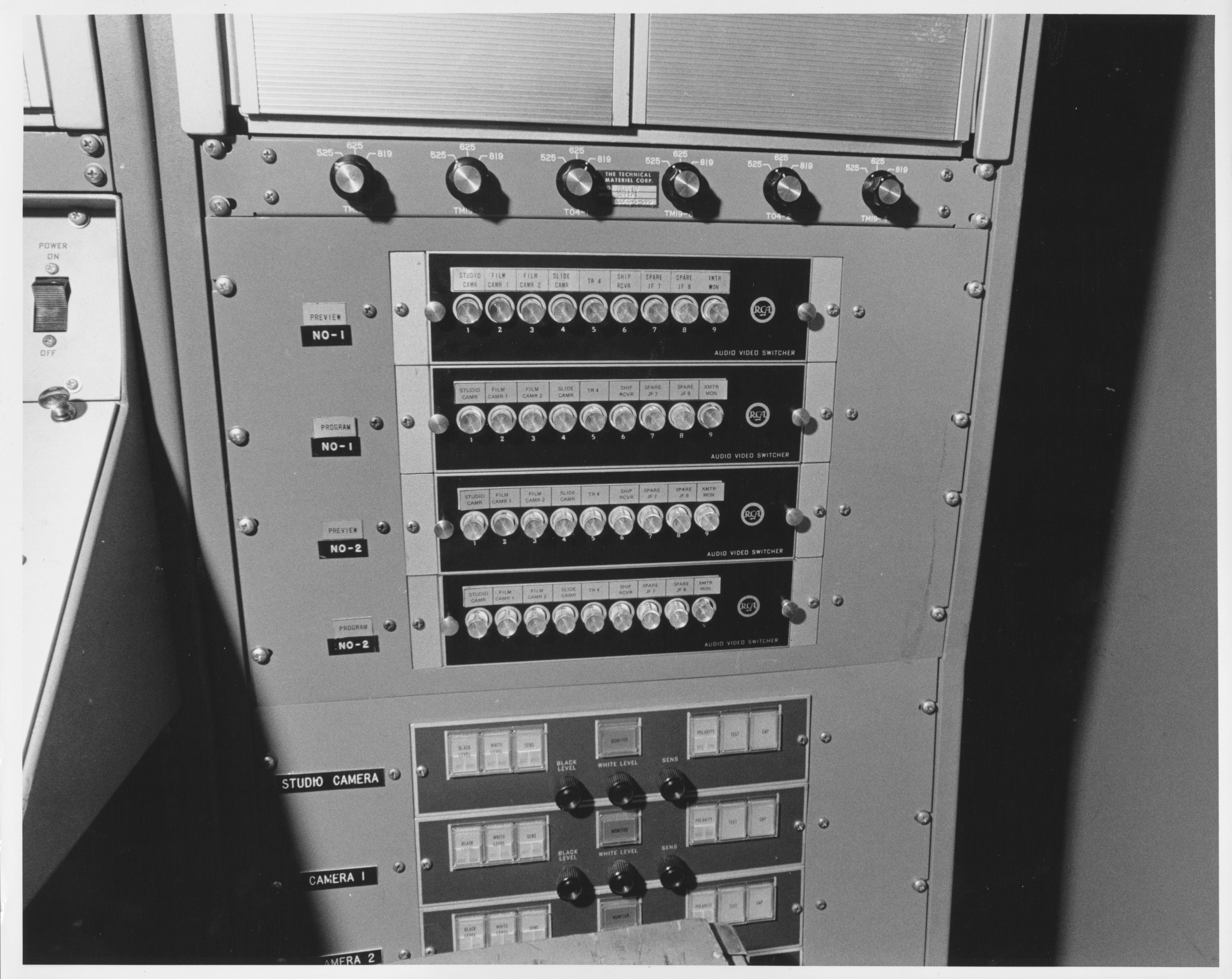
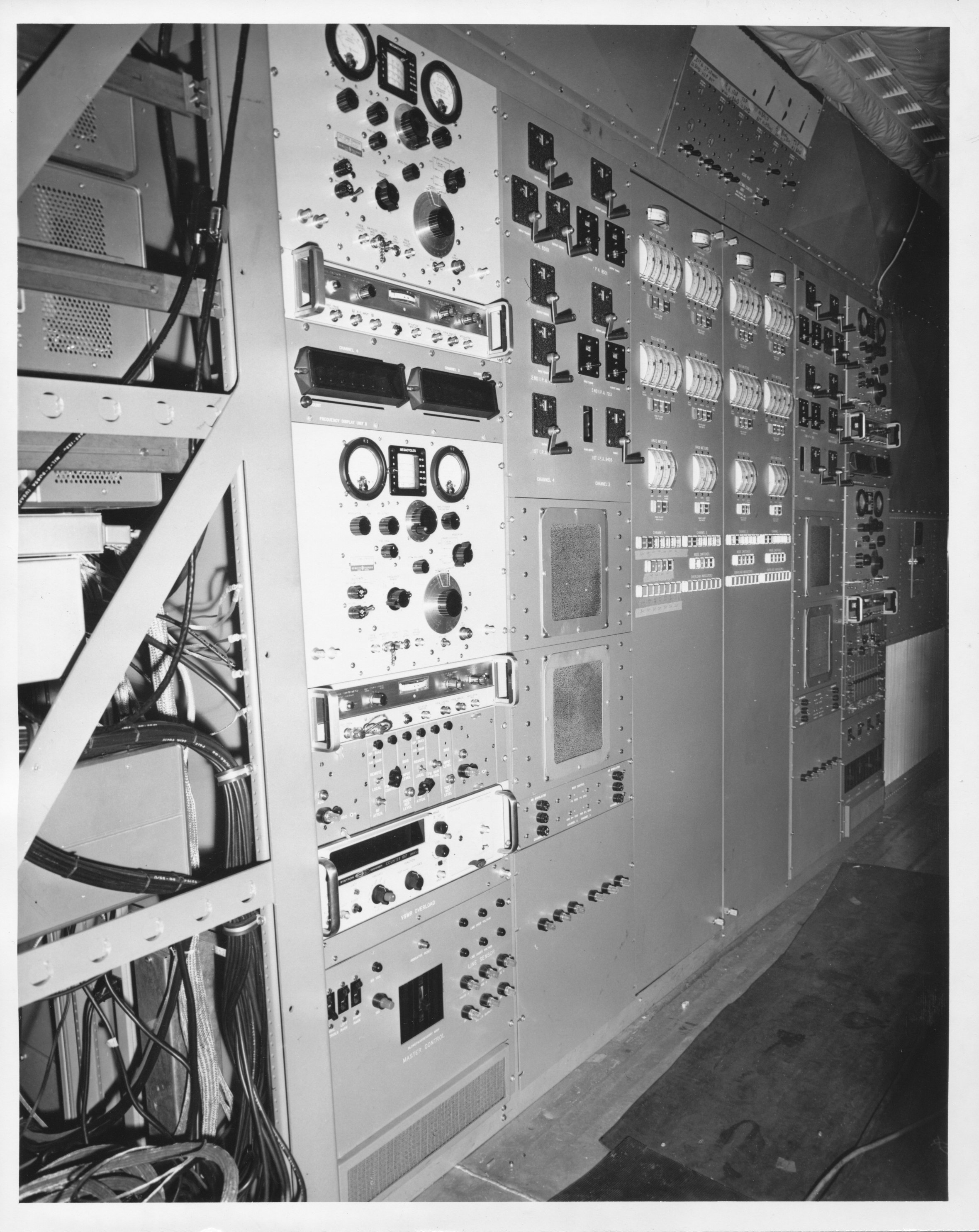
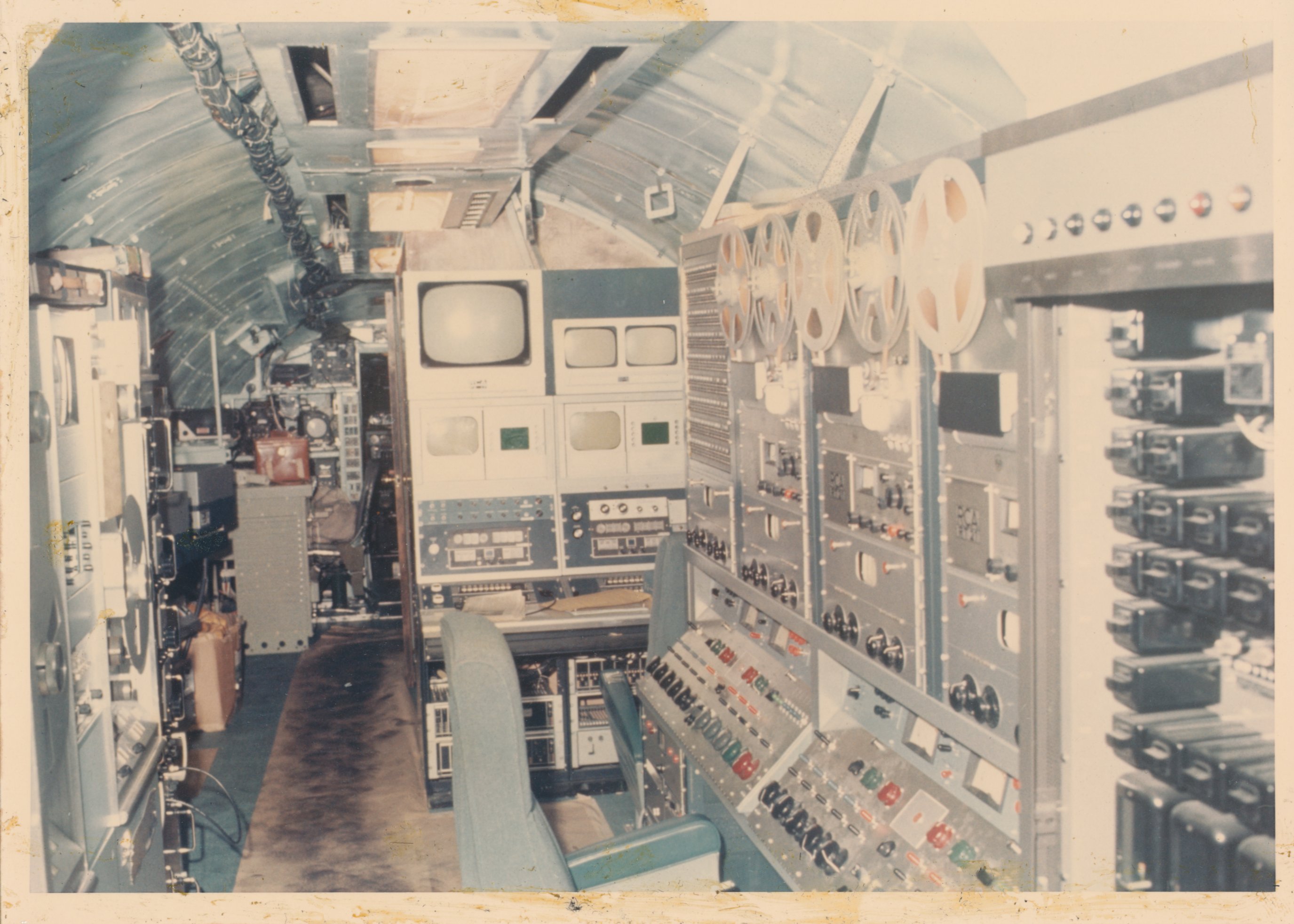
| No number, but units 13. Photo has written on back: "Both reel & cartridge tape recorders and all radio receiver information is processed here for presentation to central control console. Companders provide high quality processing of audio information." | No number, but clearly unit 17. Photo has written on back: "Command control console. Right rack provides complete control of all transmitted information as well as monitor of all receive channels. Spectrum analyzers & video picture monitors provide visual presentation." | 681.15-9 Aircraft model. Sadly, resolution is not quite high enough to read the diagram on the wall!! The aircraft is pretty clearly Blue Eagle I, but the equipment shown is fairly different from the photo to the right. Any help on figuring out the differences would be gratefully accepted! | This photo appears to show Blue Eagle I, configured quite differently from the plane shown to the left. From discussions with John Showalter, I believe this was the initial configuration of BE-I, with a TMC diesel generator, a GPT-10K, a GPT-10KLF, a sound-proofed studio (just aft the cockpit), the trailing wire antenna system, the dipole antenna coupler (aft), and a bunch of HF comm's gear, which Dixon, a ham, evidently used quite a bit during test flights! |
 |
 |
 |
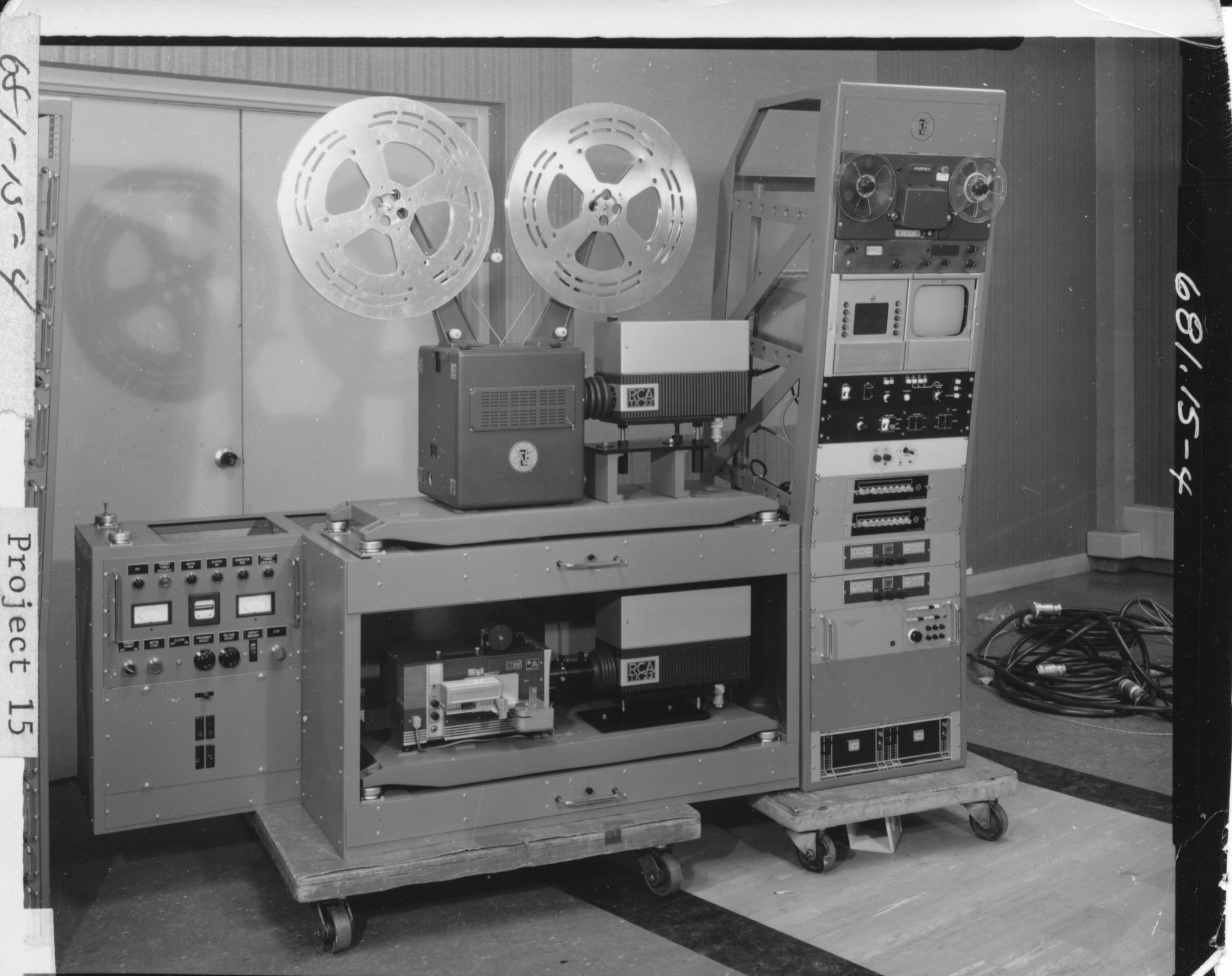 |
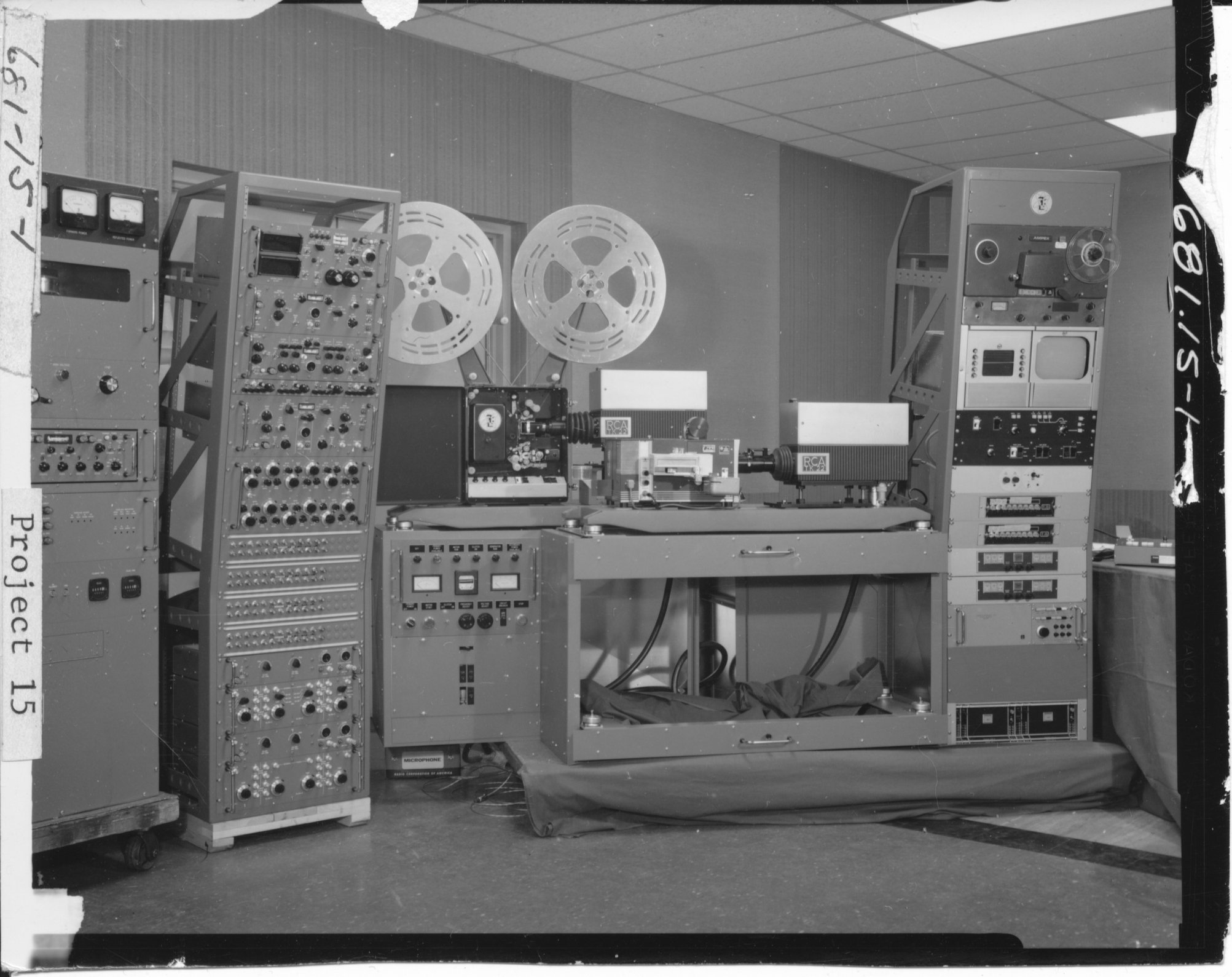
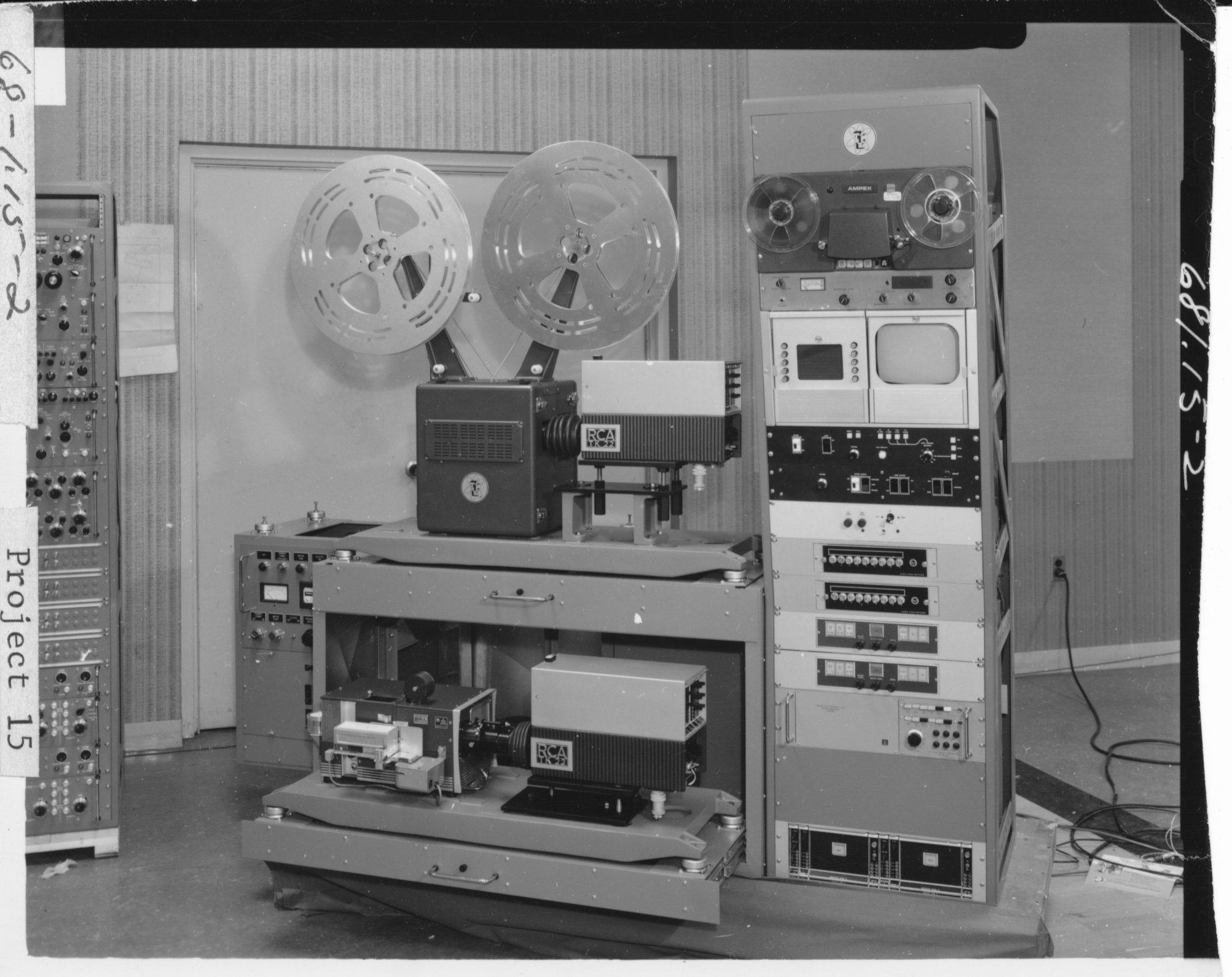
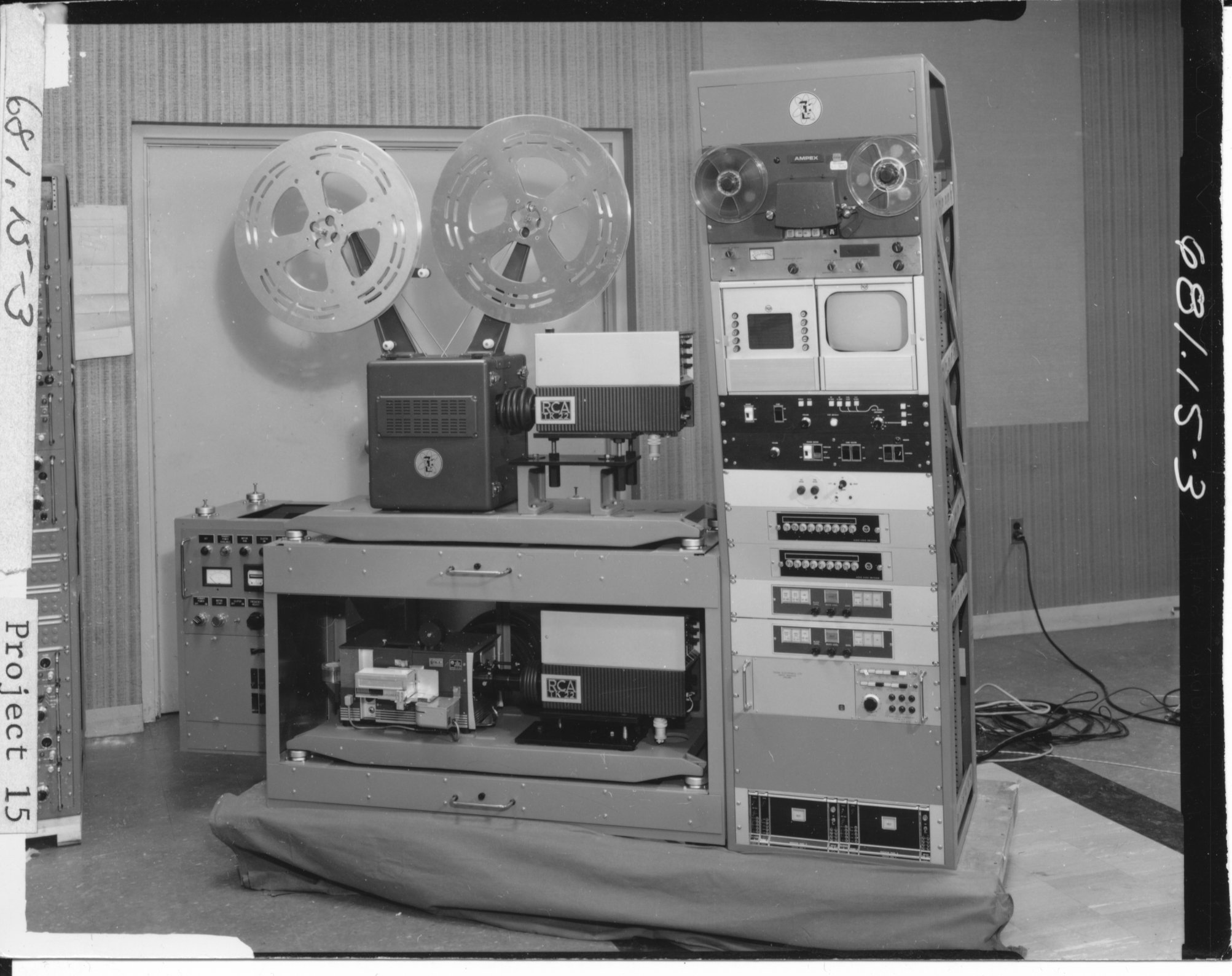
| 681-15.1 Camera chain photo with other racks. | 681.15-2 | 681.15-3 | 681.15-4 |
 |
 |
 |
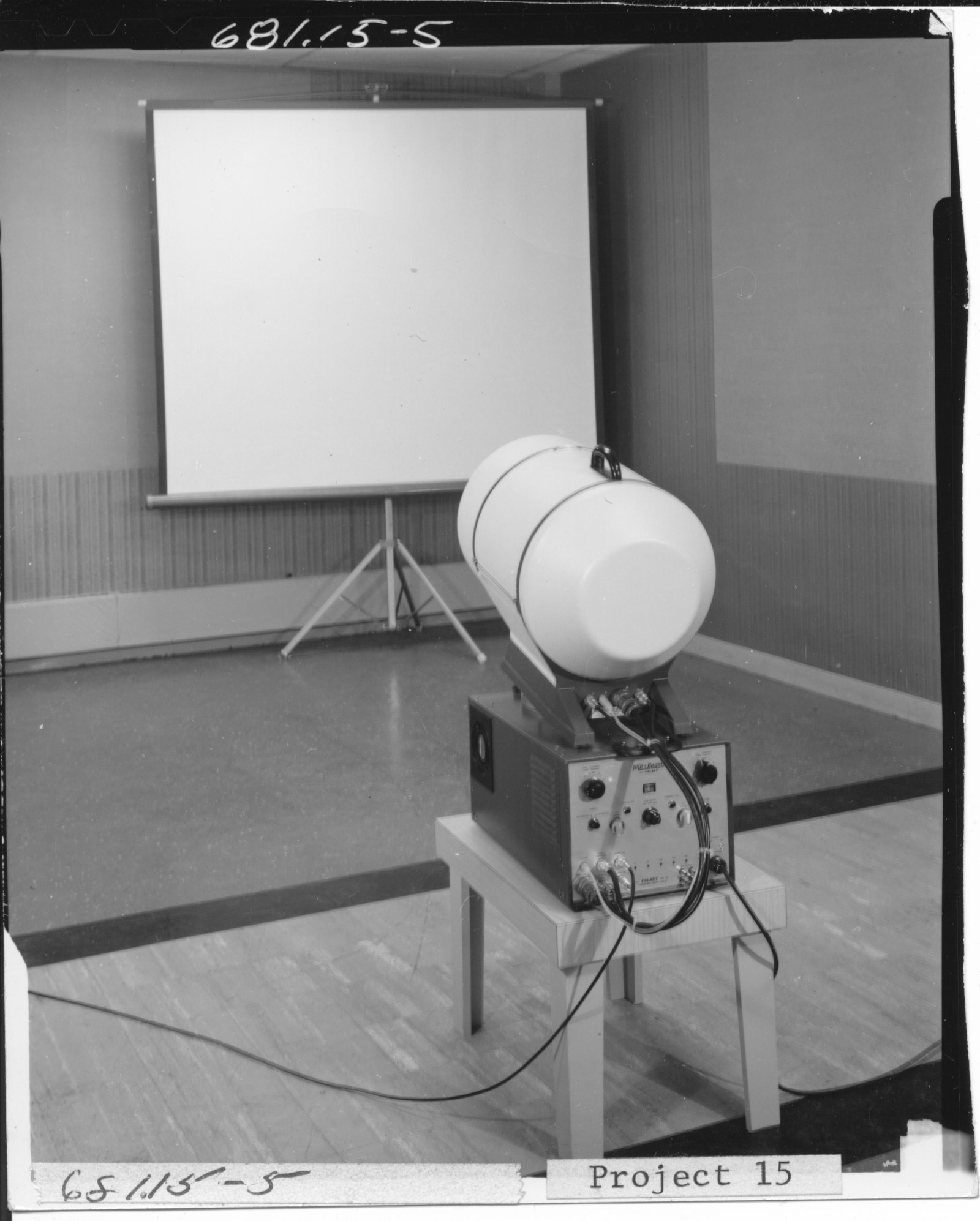 |
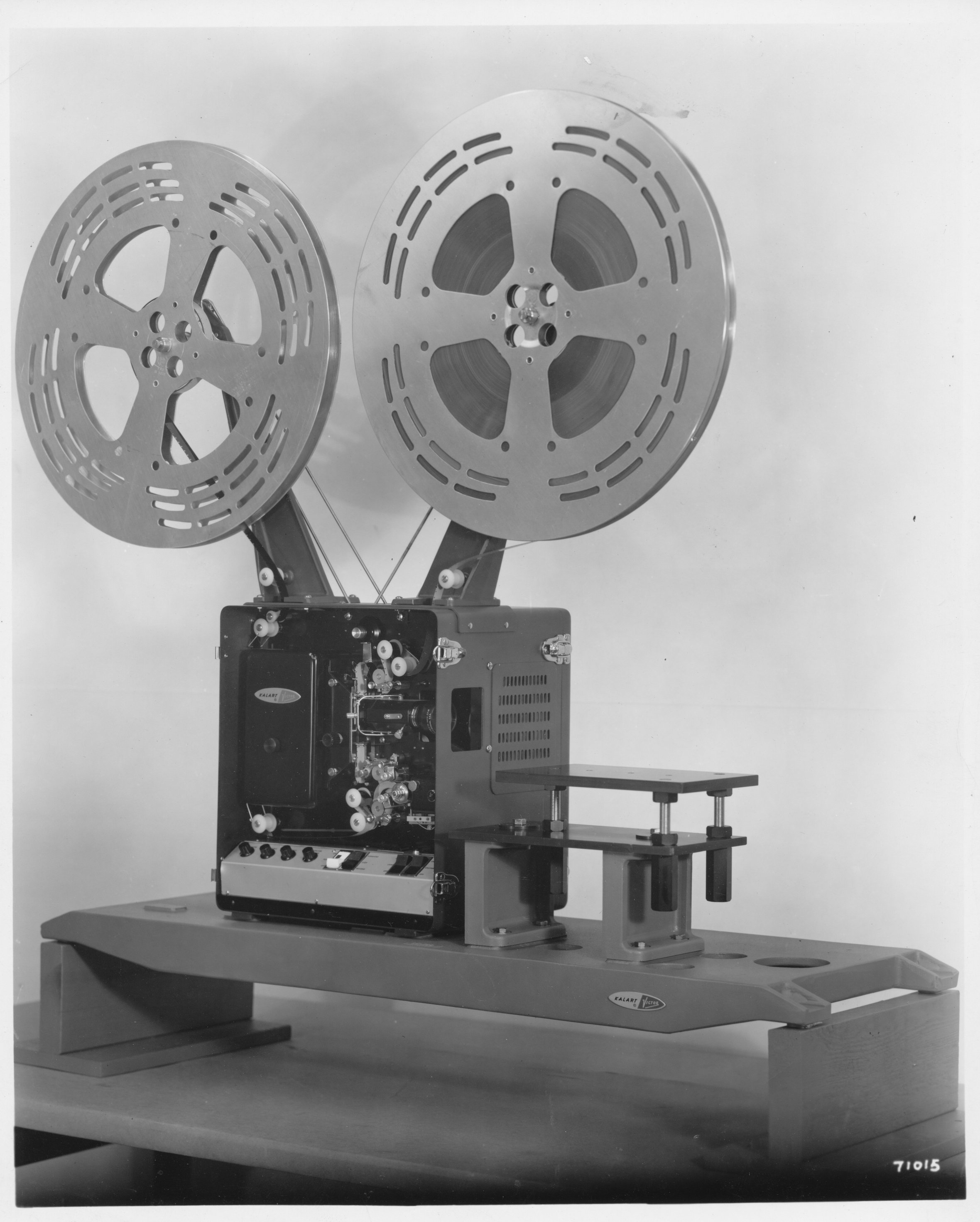
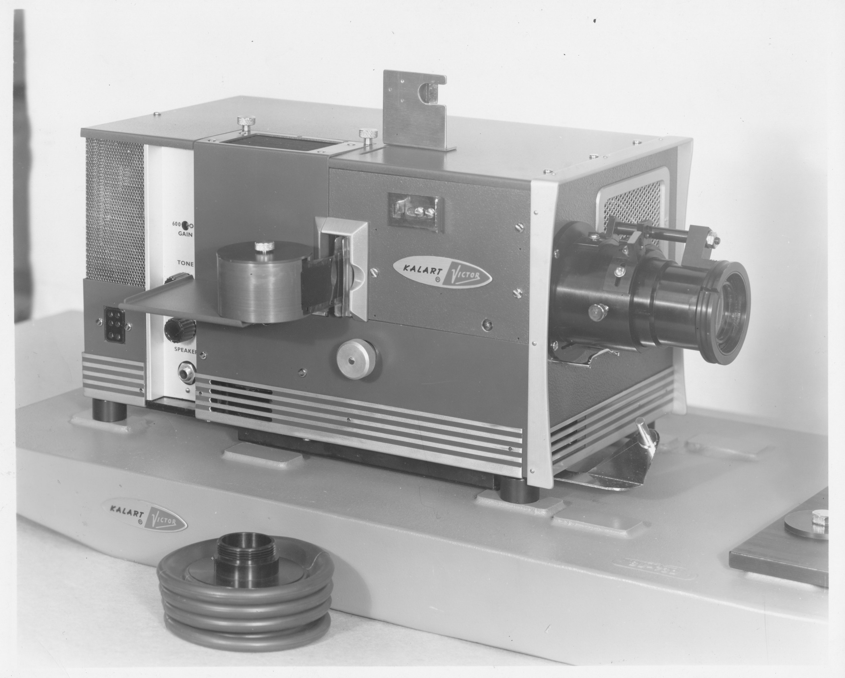
| Not labeled, but obviously the film projector from the "camera chain". | These two shots show closeups of the slide projector in the "camera chain". | 681.15-5. This appears to be a TV projection system. Not clear what it was used for. | |
 |
 |
 |
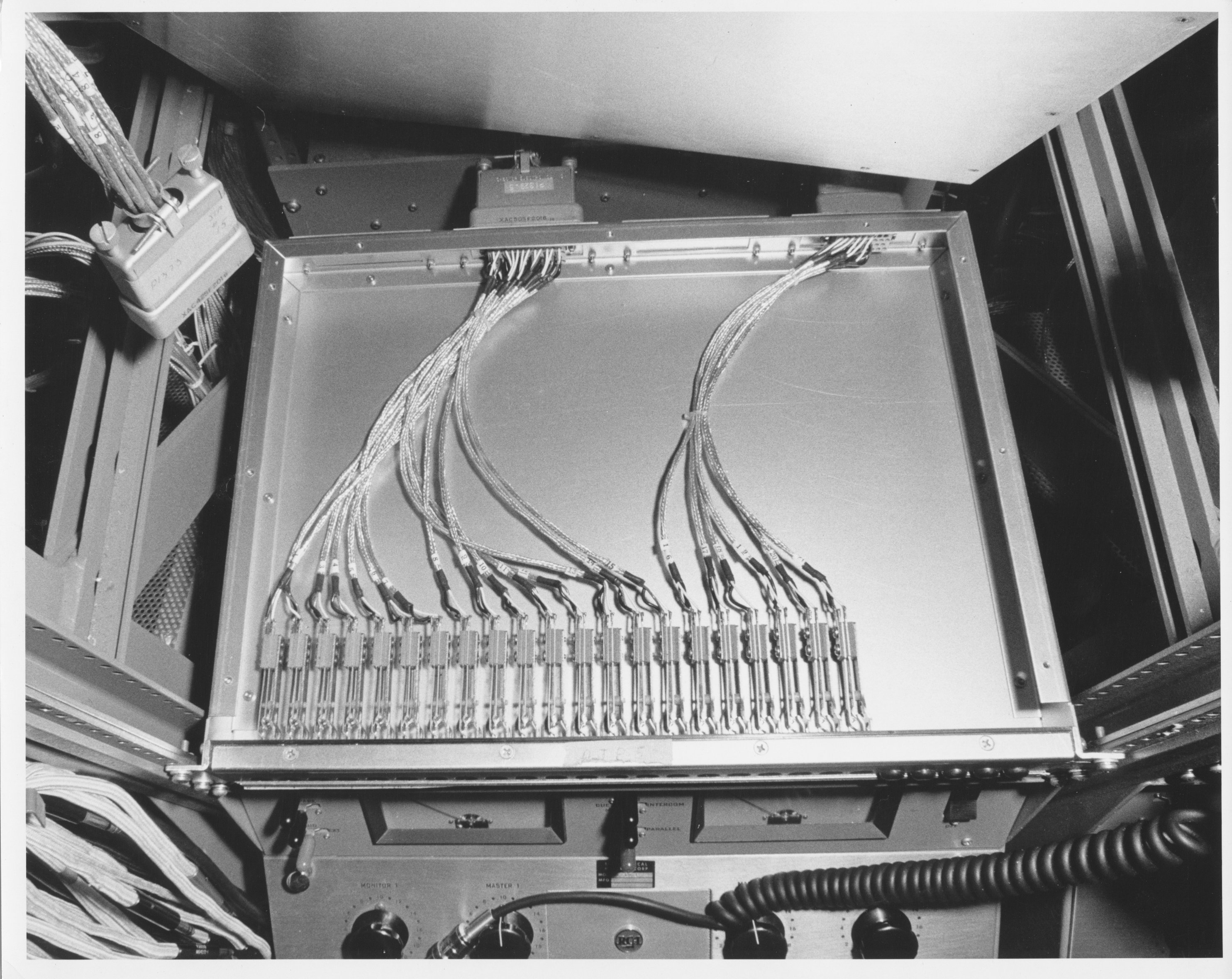 |
| C706.4-A36 Speaker unit at top of Unit 11 | C706.4-A24 Lower center portion of Unit 13A | C706.4-A30 Patch panel, first of 4 layers in Unit 13B | |
 |
 |
 |
 |
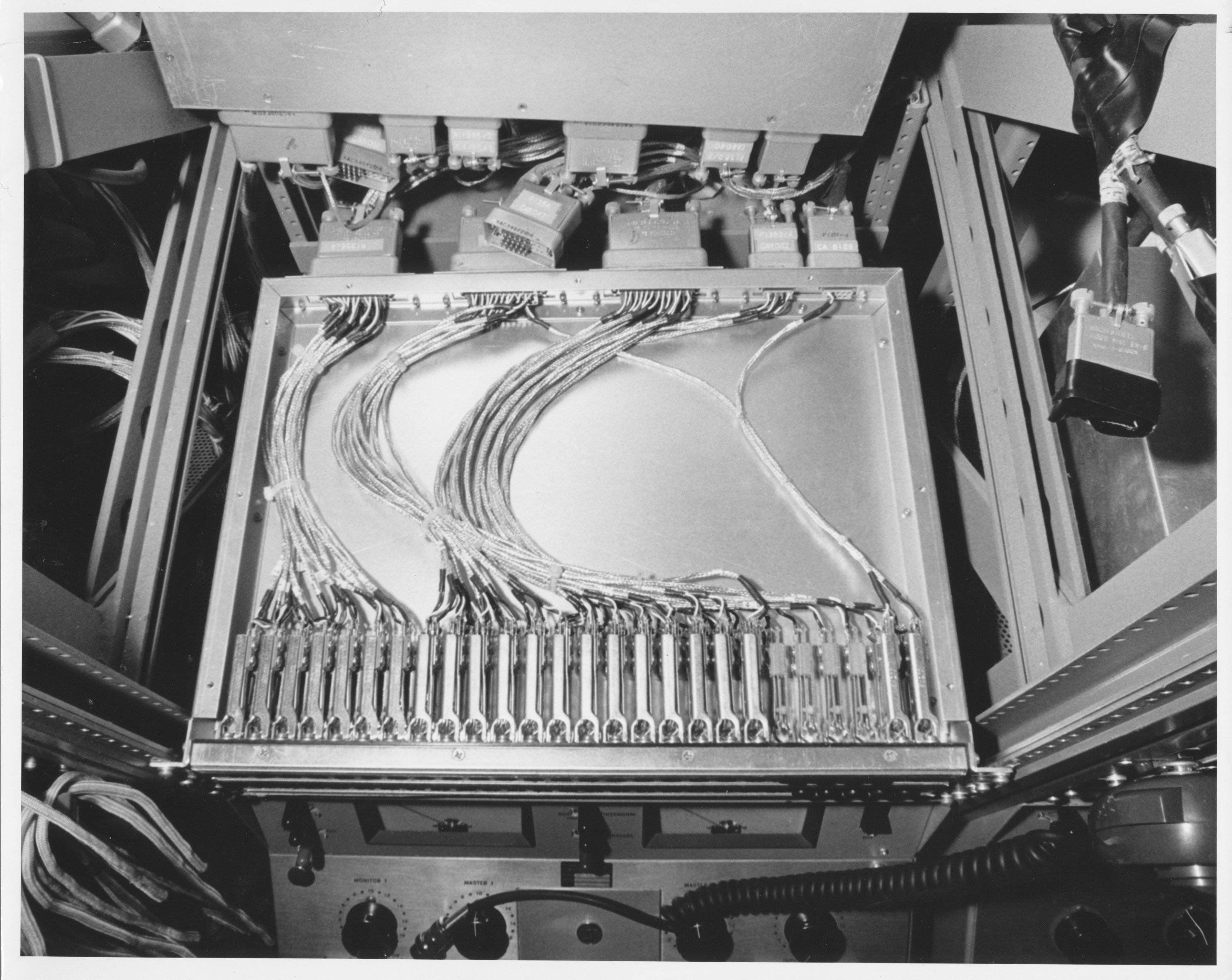
| C706.4-A29 2nd patch panel in 13B | C706.4-A28 3rd patch panel | C706.4-A27 4th patch panel | C706.4-A25 A closeup of unit 13C |
 |
 |
 |
 |
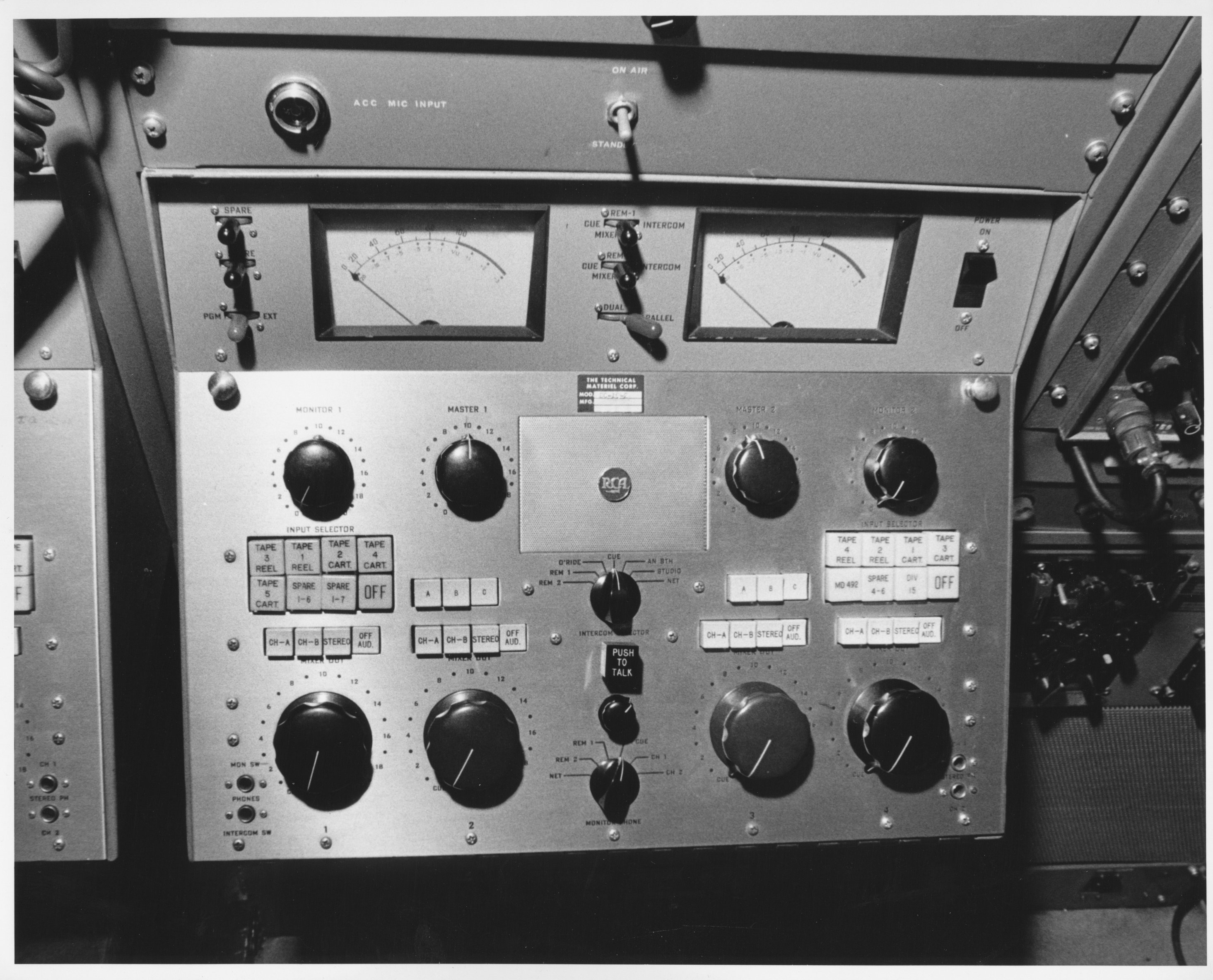
| C706.4-A26 Closeup of TMC-built unit directly above tape controls in Unit 13C | C706.4-A9 Closeup of controls in Unit 13 C | C706.4-A3 Closeup of portion of Unit 14A | C706.4-A35 Units 16 E,D,C |
 |
 |
 |
 |
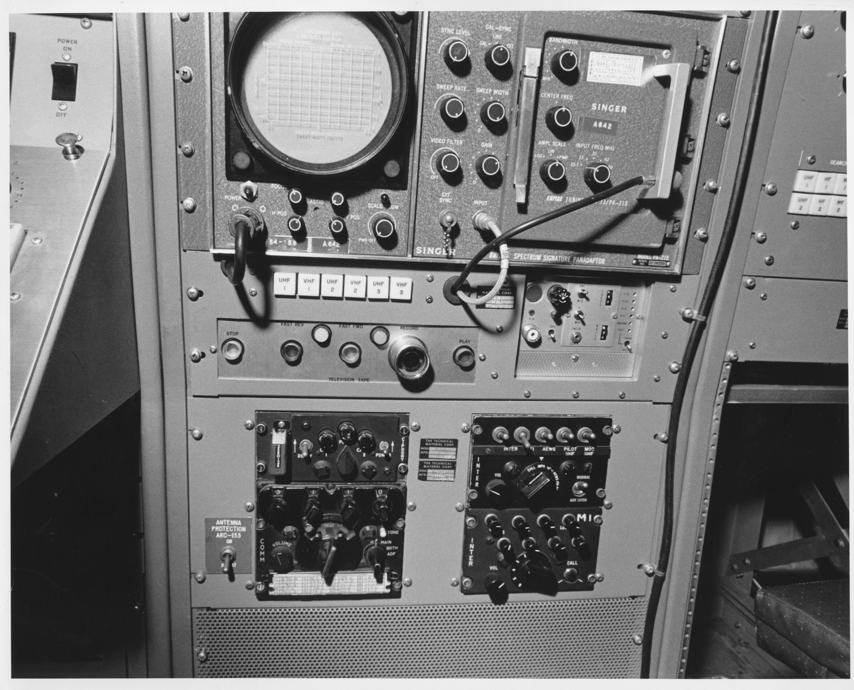
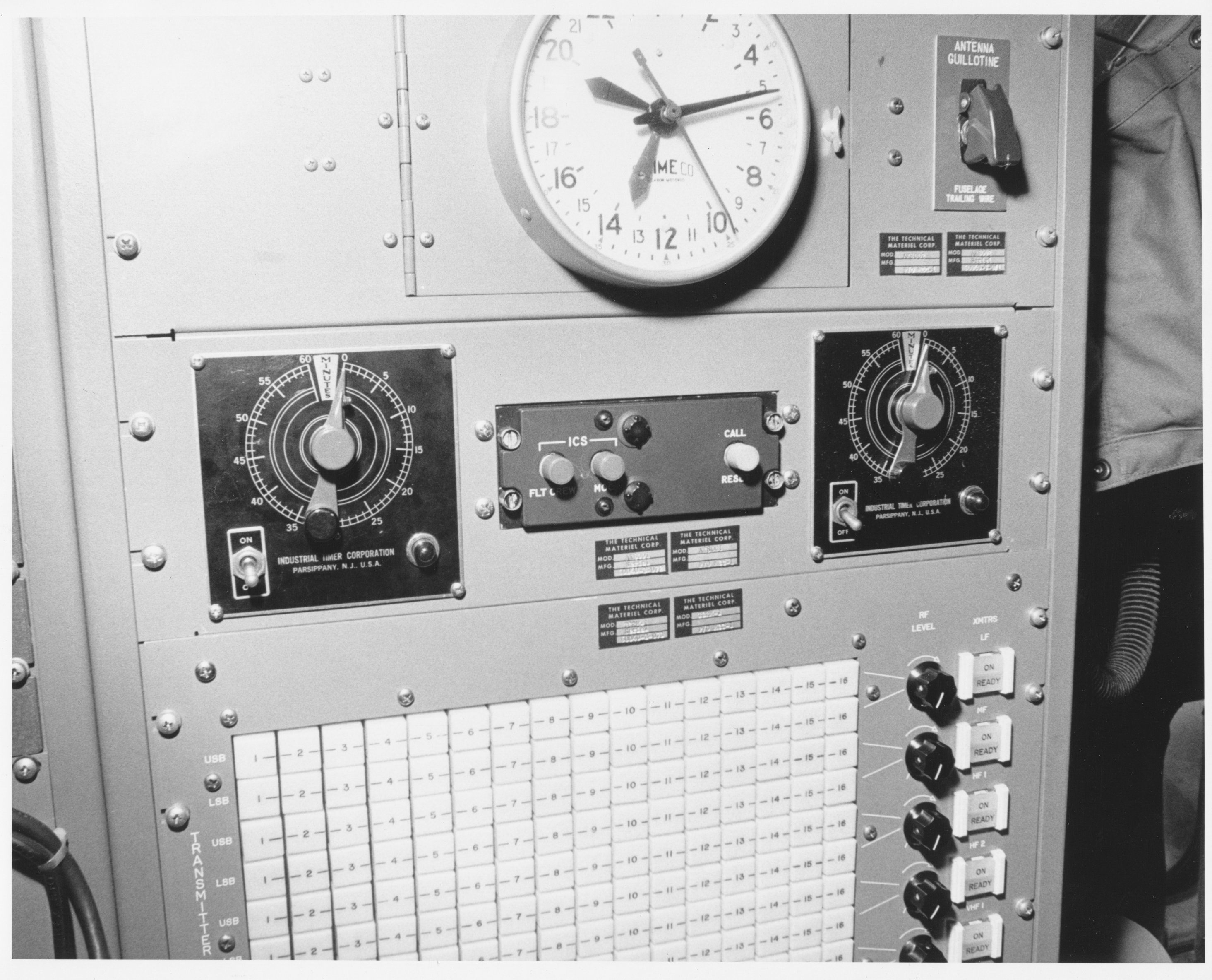
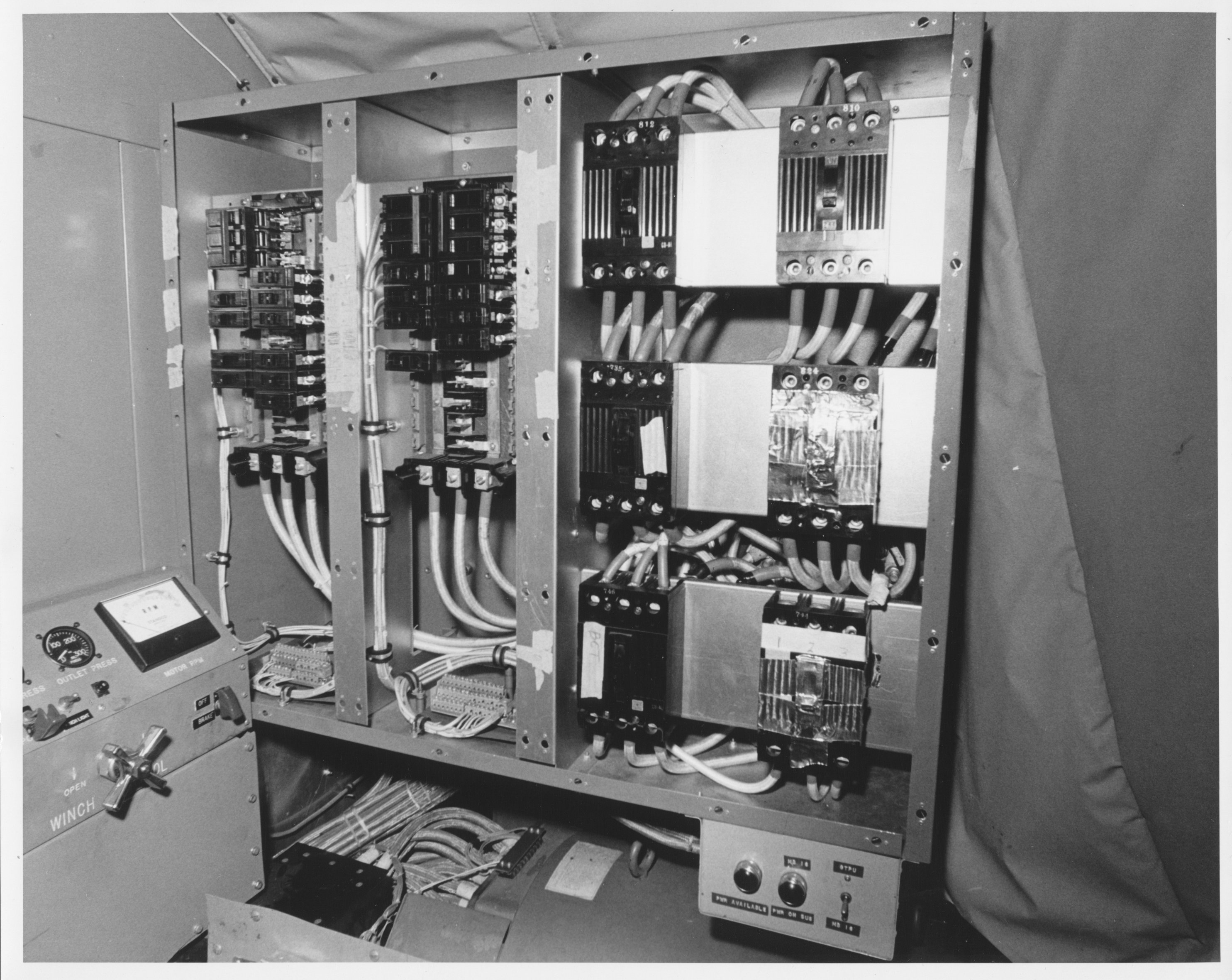
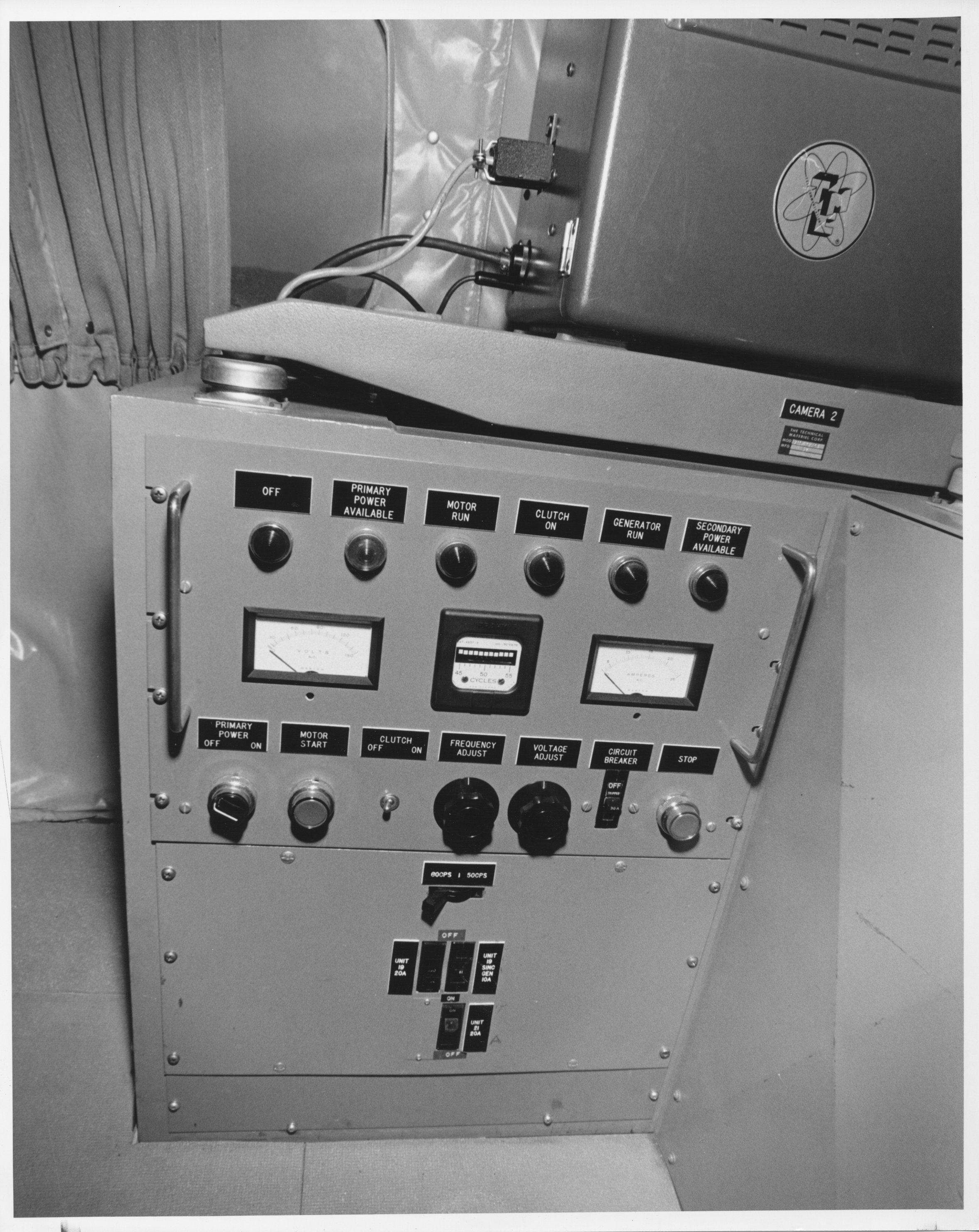
| C706.4-A8 Closeup of Unit 17 | C706.4-A4 Another closeup of Unit 17 | C706.4-A5 Closeup of Unit 17 upper right | C706.4-A2 AC Distribution panel (right), and perhaps trailing-wire winch left. |
 |
 |
 |
 |
| C706.4-A31 AC distribution panel with front panel removed | C706.4-B23 Between-seats console. | No number. Aircraft interior shot #1. | No number. Aircraft interior shot #2. |
 |
 |
 |
 |
| No number. Aircraft interior shot #3. | C706.4-A17. Camera chain overall. | C706.4-A22. Camera chain panel closeup. | C706.4-A13. Another panel closeup. |
 |
 |
 |
 |
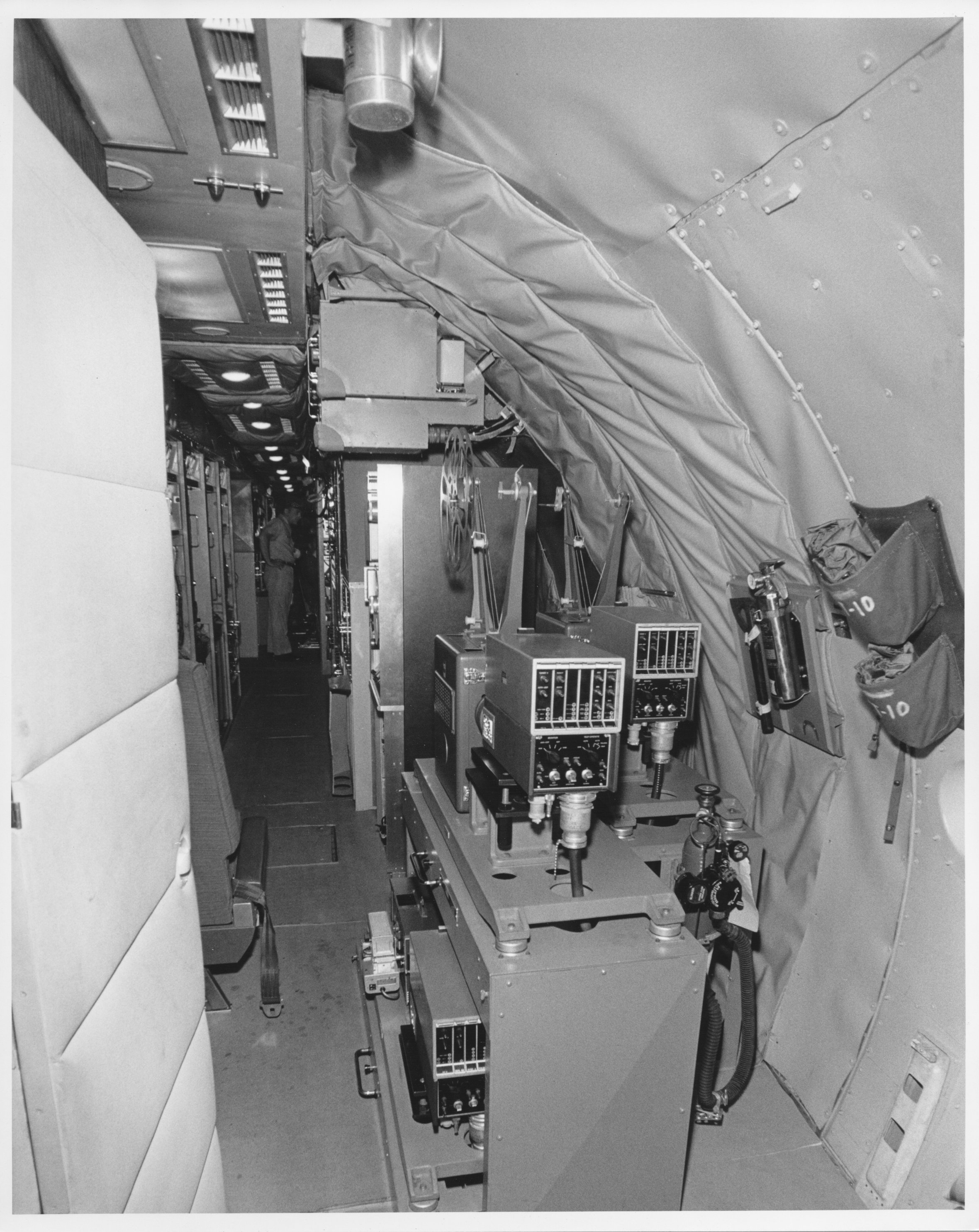
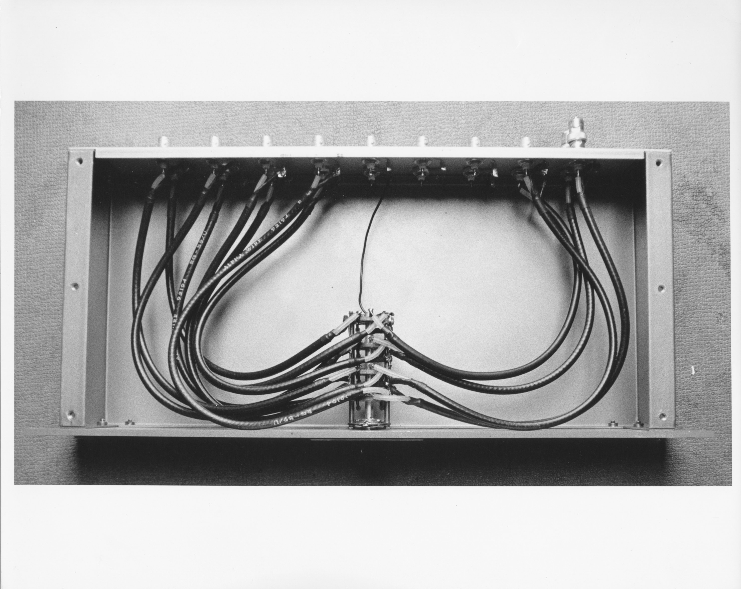
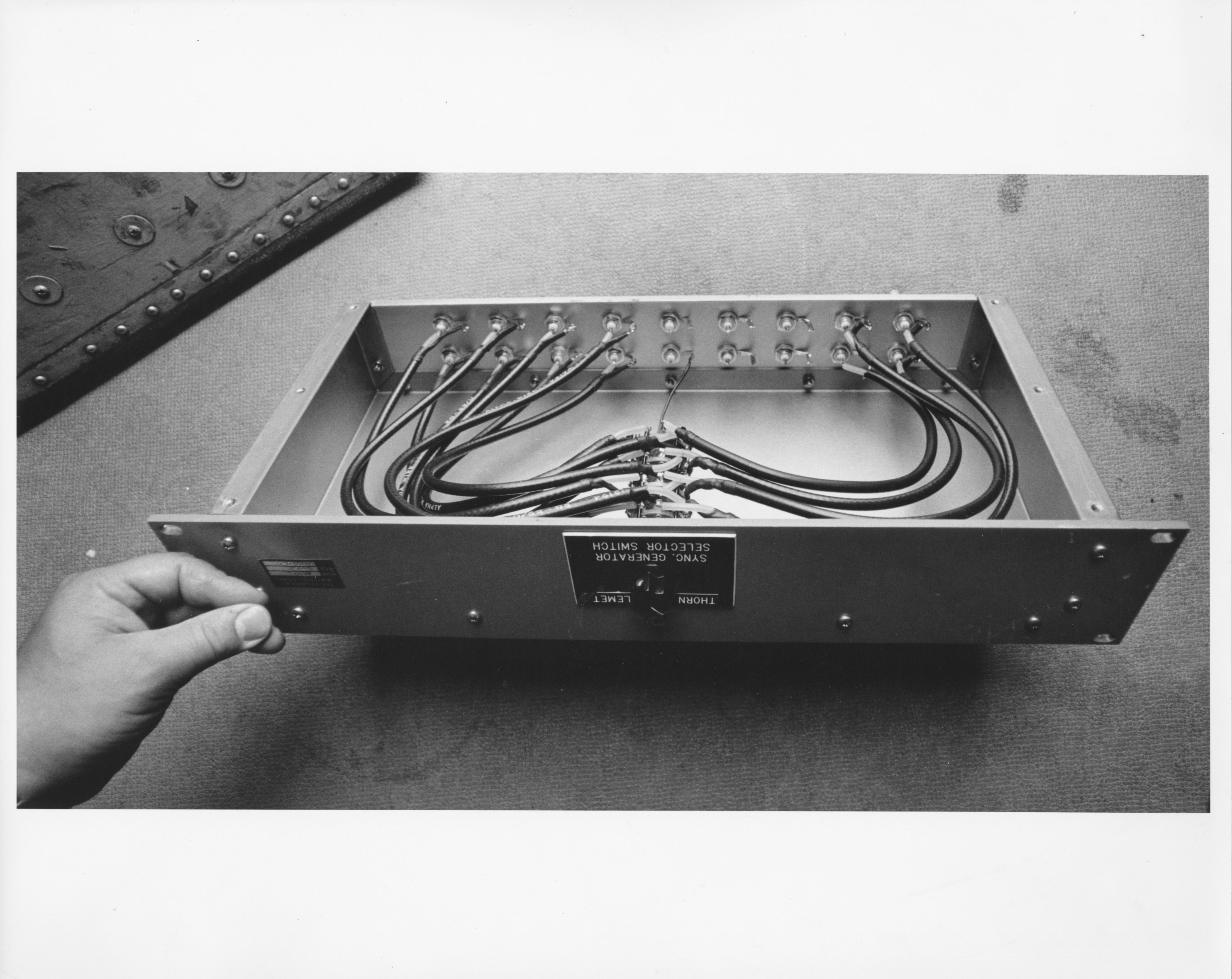
| C706.4-A18. View of camera chain from rear(?) of aircraft. | C706.4-A10. Sync switch bottom | C706.4-A11. Sync switch overall. | C706.4-B25. TV camera and console. This unit was used in conjunction with the seats and control consoles shown in photo C706.4-B23, forming the airborne TV studio. The camera could be controlled from the console, and the outgoing image could be viewed on the monitor. |
 |
 |
 |
 |
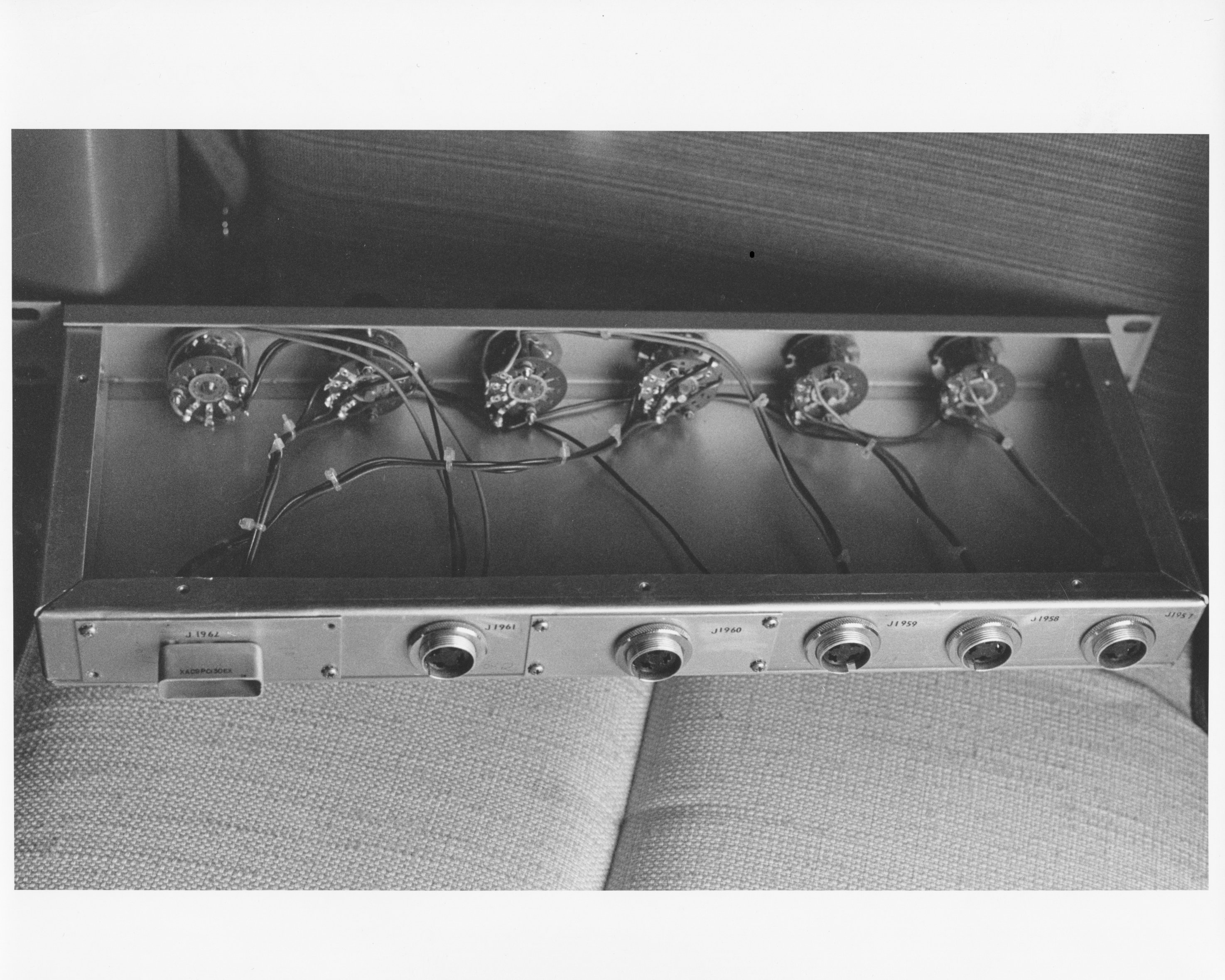
| C706.4-A20 Unknown unit. | C706.4-C1 Switch unit inside the unknown unit of C706.4-A20 | C706.4-A19. Unknown switch unit. |
No photo number, but this is the same SPT-3KVHF transmitter shown above in the "units" gallery. |
 |
 |
 |
 |
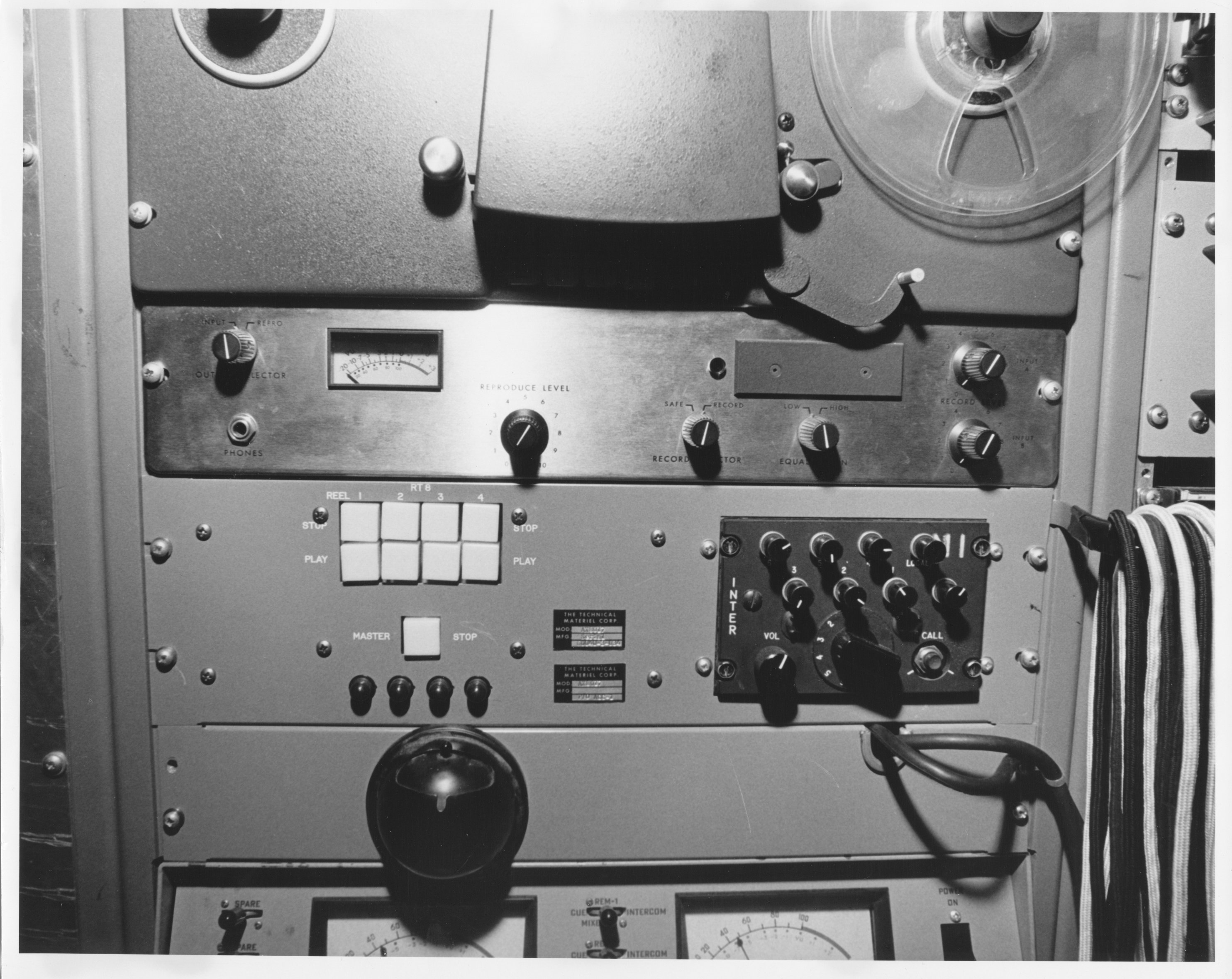
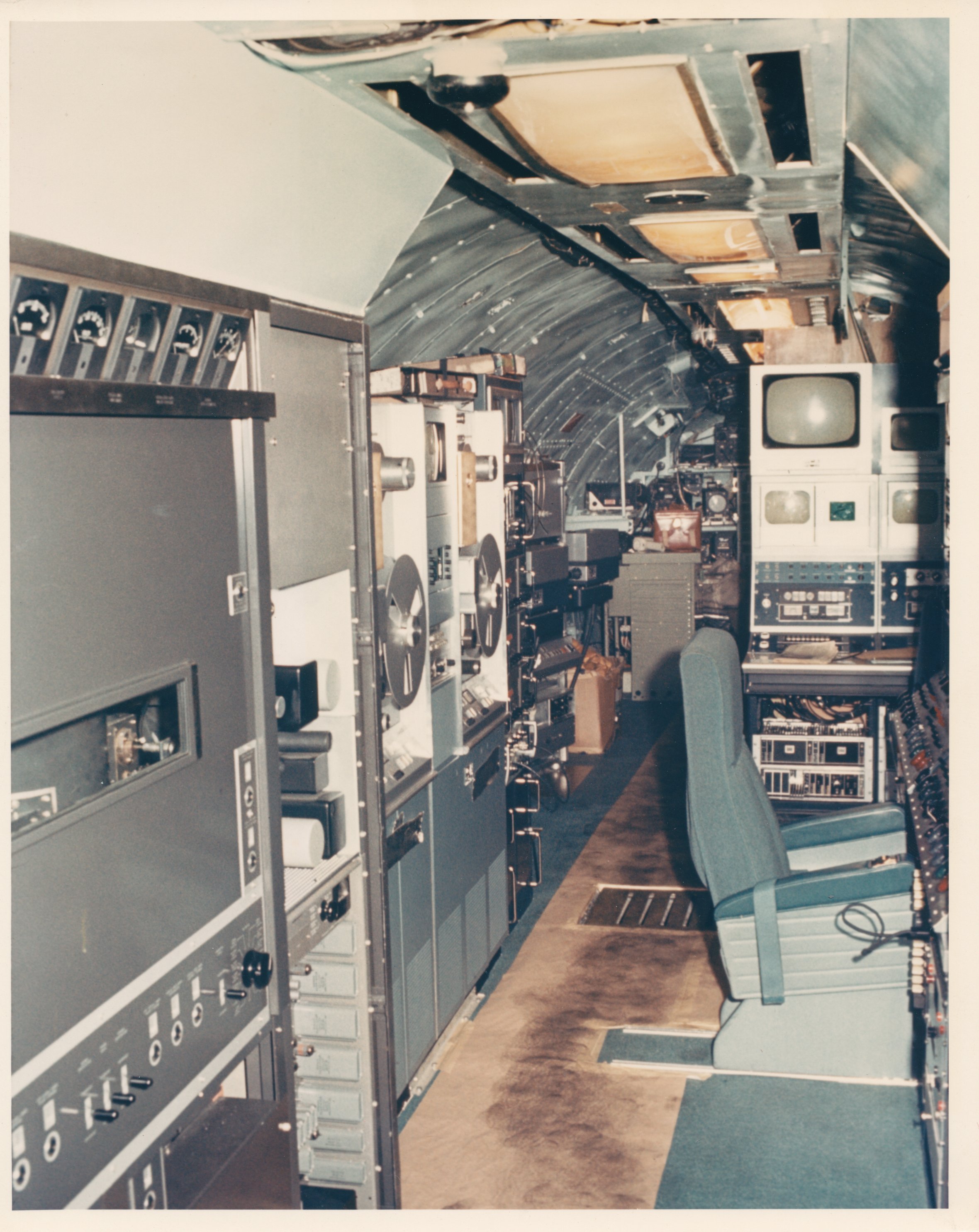
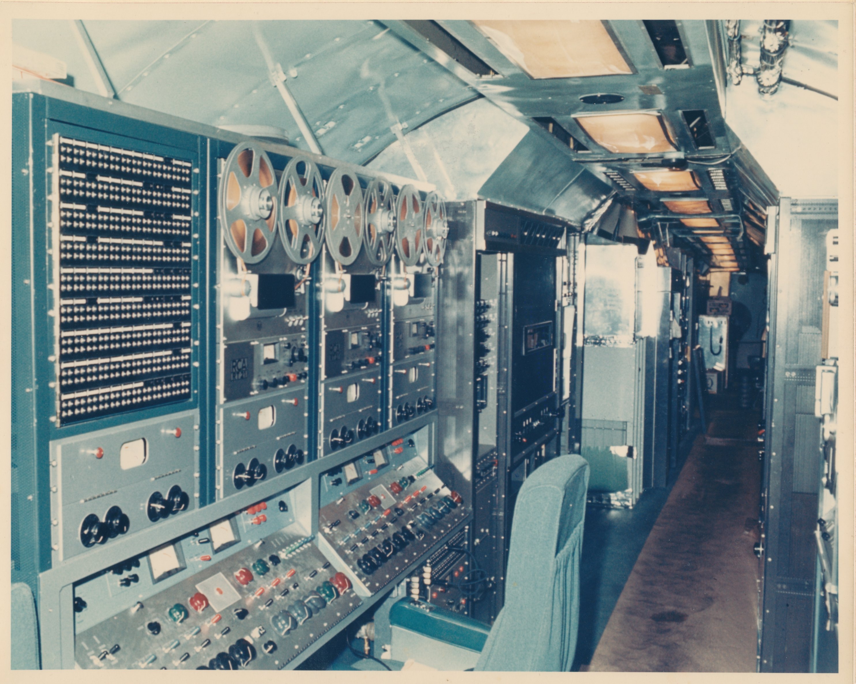
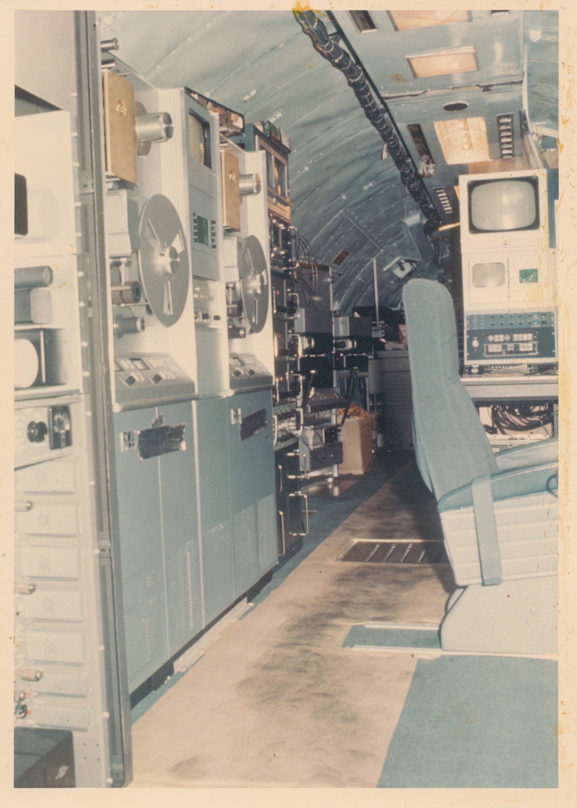
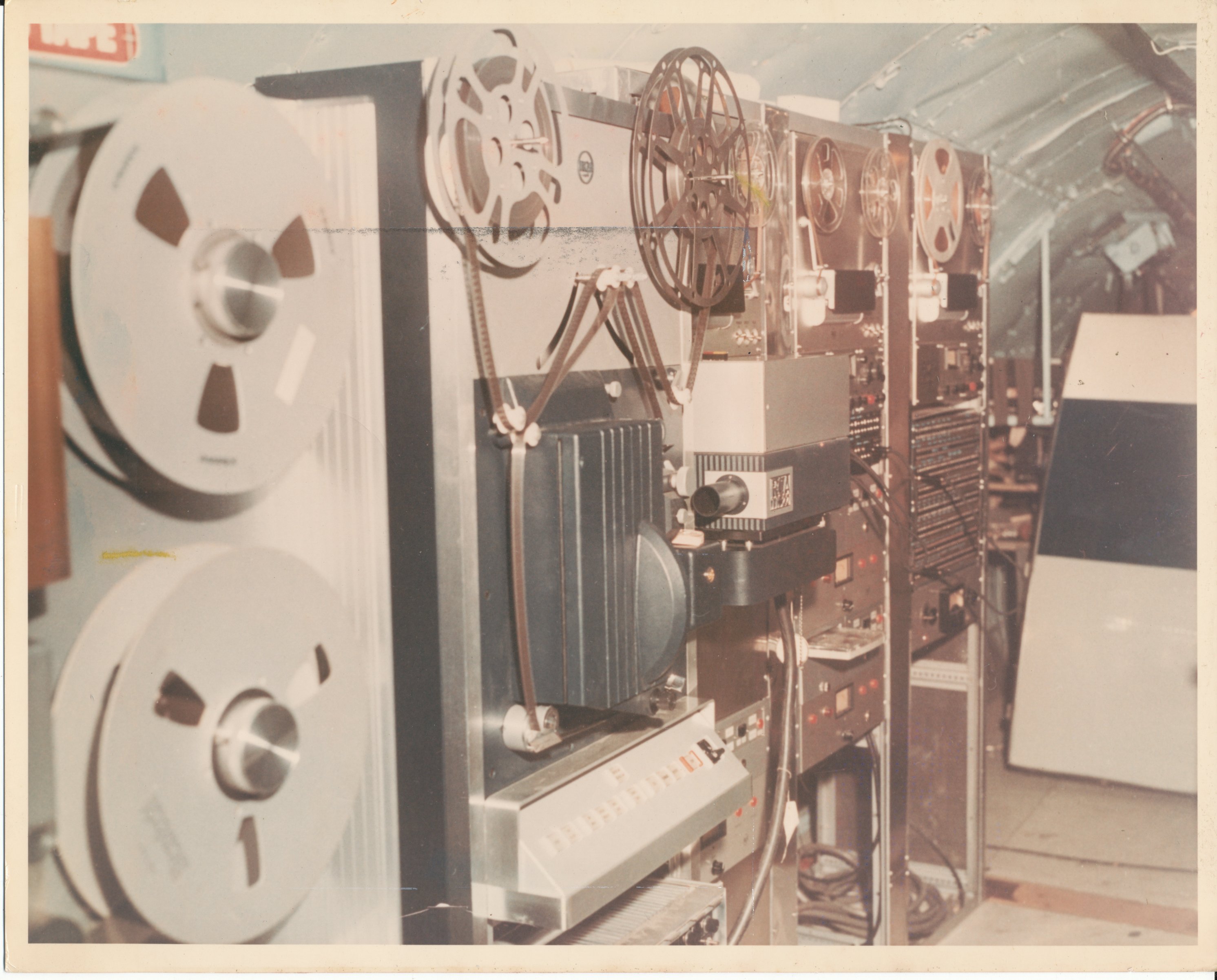
| These two photos show Units 13A,B,C with audio tapes installed. One view is aft, one for'ard, but I'm not sure which. | This interior photo shows a pair of huge video tape players. | This photo shows a couple of film-to-video systems. These units are just barely visible behind the VTR's in the photo to the left. | |
 |
|||
| No number. This photo is labeled on the back: "TV video tape recorder; TV (missing) mm film projector; Audio tape recorders." | |||